


153
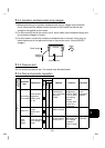
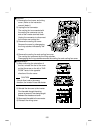
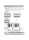
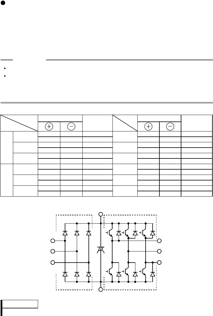
Checking the inverter and converter modules
<Preparation>
(1) Disconnect the external power supply cables (R, S, T) and motor cables (U, V, W).
(2) Prepare a meter. (Use 100Ω range.)
<Checking method>
Change the polarity of the meter alternately at the inverter terminals R, S,
T, U, V, W, P and N, and check for continuity.
CAUTION
Before measurement, check that the smoothing capacitor is discharged.
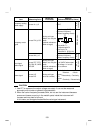
At the time of continuity, the measured value is several to several ten's-of ohms
depending on the number of modules, number of parallel modules, circuit tester
type, etc. If all measured values are almost the same, the modules are without
fault.
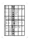
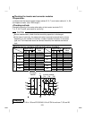
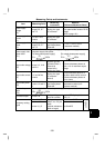
<Module device numbers and terminals to be checked>
Tester Polarity Tester Polarity
Measured
Value
Measured
Value
R P Discontinuit
y
R N Continuity
D1
P R Continuity
D4
N R Discontinuit
y
S P Discontinuit
y
S N Continuity
D2
P S Continuity
D5
N S Discontinuit
y
T P Discontinuit
y
T N Continuity
Converter
module
D3
P T Continuity
D6
N T Discontinuit
y
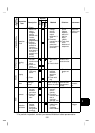
U P Discontinuit
y
U N Continuity
TR1
P U Continuity
TR4
N U Discontinuit
y
V P Discontinuit
y
V N Continuity
TR3
P V Continuity
TR6
N V Discontinuit
y
W P Discontinuit
y
W N Continuity
Inverter
module
TR5
P W Continuity
TR2
N W Discontinuit
y
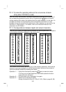
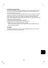
(Assumes the use of an analog meter.)
Converter
module Inverter module
D1 D2 D3
D4 D5 D6
TR1 TR3 TR5
TR4 TR6 TR2
U
V
W
R
S
T
C
P
N
REMARKS
The FR-S520S-0.1K to 1.5K and FR-S510W-0.1K to 0.75K do not have T, D3 and D6.