


3
1
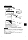
CAUTION
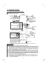
To prevent a malfunction due to noise, keep the signal cables more than 10cm (3.94inches)
away from the power cables.
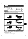
FR-S520S-0.1K to 1.5K (-R) (-C)
FR-S510W-0.1K to 0.75K (-R)
Power supply
NFB
R
S
Motor
IM
Earth
(
Ground
)
U
V
W
MC
REMARKS
•
To ensure safety, connect the power input to the inverter via a magnetic contactor and earth
leakage circuit breaker or no-fuse breaker, and use the magnetic contactor to switch power on-off.
•
The output is three-phase 200V.
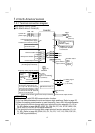
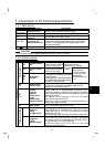
1
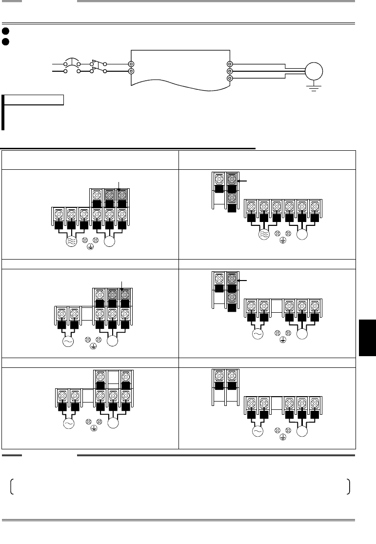
.1.2 Layout and wiring of main circuit terminals
FR-S520-0.1K, 0.2K, 0.4K, 0.75K
(
-R
)
(
-C
)
FR-S520-1.5K, 2.2K, 3.7K (-R) (-C)
FR-S540-0.4K, 0.75K, 1.5K, 2.2K, 3.7K
(
-R
)
P1
U
V
W
IM
RST
NP
Jumper
Power supply Motor
P1
Jumper
R S
T
U
V
W
IM
NP
Power supply Motor
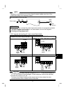
FR-S520S-0.1K, 0.2K, 0.4K, 0.75K (-R) FR-S520S-1.5K (-R)
P1
U
V W
IM
NP
RS
Jumper
Power supply Motor
P1
U V
W
IM
N
P
RS
Jumper
Power supply Motor
FR-S510W-0.1K, 0.2K, 0.4K (-R) FR-S510W-0.75K (-R)
U
V W
IM
NP
RS
Power supply Motor
U
V
W
IM
NP
RS
Power supply
Motor
CAUTION
•
The power supply cables must be connected to R, S, T. If they are connected to U, V, W,
the inverter will be damaged. (Phase sequence need not be matched.)
For use with a single-phase power supply, the power supply cables must be connected to
R and S.
•
Connect the motor to U, V, W.
Turning on the forward rotation switch (signal) at this time rotates the motor
counterclockwise when viewed from the load shaft.