


122
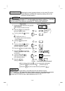
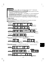
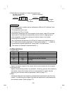
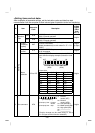
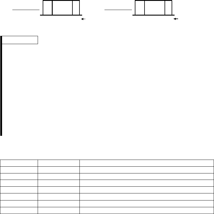
4) Send data from computer to inverter during data read
*3
ACK
*4
Number
of
characters
Inverter
station
number
1234
Format G Format H
[No data error detected] [Data error detected]
Number
of
characters
*3
NAK
*4
Inverter
station
number
1234
(May be omitted)
REMARKS
• The inverter station numbers may be set between H00 and H1F (stations 0 and
31) in hexadecimal.
• *3 indicates the control code.
• *4 indicates the CR or LF code.
When data is transmitted from the computer to the inverter, codes CR (carriage
return) and LF (line feed) are automatically set at the end of a data group on
some computers. In this case, setting must also be made on the inverter
according to the computer.
Also, the presence and absence of the CR and LF codes can be selected using n11.
• At *5, when communication parameter n7 "waiting time setting" ≠ - - -, create the
communication request data without "waiting time" in the data format.
(The number of characters is decremented by 1.)
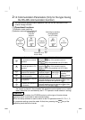
(4) Data definitions
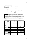
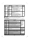
1) Control codes
Signal ASCII Code Description
STX H02 Start of Text (Start of data)
ETX H03 End of Text (End of data)
ENQ H05 Enquiry (Communication request)
ACK H06 Acknowledge (No data error detected)
LF H0A Line Feed
CR H0D Carriage Return
NAK H15 Negative Acknowledge (Data error detected)
2) Inverter station number
Specify the station number of the inverter which communicates with the computer.
3) Instruction code
Specify the processing request, e.g. operation, monitoring, given by the computer to
the inverter. Hence, the inverter can be run and monitored in various ways by
specifying the instruction code as appropriate. (Refer to page 177.)
4) Data
Indicates the data such as frequency and parameters transferred to and from the
inverter. The definitions and ranges of set data are determined in accordance with
the instruction codes. (Refer to page 177.)