


42
(2) RS-485 communication
Use the RS-485 connector to perform communication operation from a personal
computer etc.
By connecting the RS-485 connector to a computer such as a personal computer,
Factory Automation unit (HMI etc.) or other computer, by the communication
cable, you can operate/monitor the inverter and read/write the parameter values
using user programs. For parameter setting, refer to page 116.
Conforming standard: EIA Standard RS-485
Transmission format: Multidrop link system
Communication speed: Max. 19200bps
Overall extension: 500m (1640.42feet)
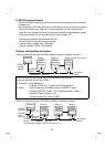
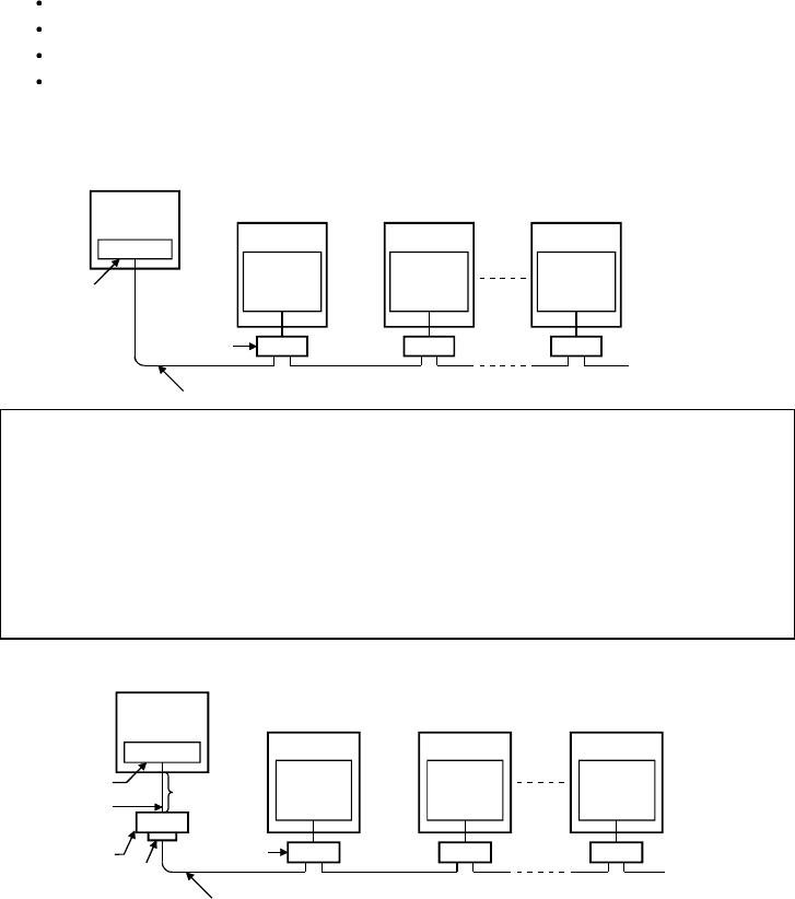
<System configuration examples>
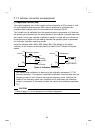
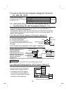
1) When a computer having a RS-485 interface is used with several inverters
Station 1
RS-485
interface
/
terminal
Computer
RS-485
connector
(*1)
RS-485
connector
(*1)
RS-485
connector
(*1)
10BASE-T cable (*2)
Distribution
terminal
Inverter
Station 2
Inverter
Station n
Inverter
Termination
resistor
(Max. 32 inverters)
Use the connectors and cables which are available on the market.
Introduced products (as of June, 2000)
*1. Connector :RJ45 connector
Example: 5-554720-3, Tyco Electronics Corporation
*2. Cable :Cable conforming to EIA568 (such as 10BASE-T cable)
Example: SGLPEV 0.5mm × 4P (Twisted pair cable, 4 pairs),
Mitsubishi Cable Industries, Ltd.
(Do not use pins No. 2 and 8 (P5S)).
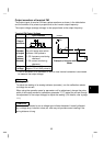
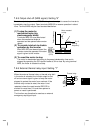
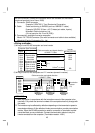
2) When a computer having a RS-232C interface is used with inverters
10BASE-T cable (*2)
RS-485
connector
(*1)
RS-232C
connector
RS-232C
cable
Station 1
Inverter
Station 2 Station n
Computer
Inverter Inverter
RS-485
connector
(*1)
RS-485
connector
(*1)
RS-485
terminal
Max. 15m
Converter*
Distribution
terminal
Termination
resistor
Commercially available converter is required. (*3)