


23
1
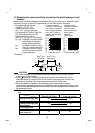
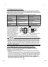
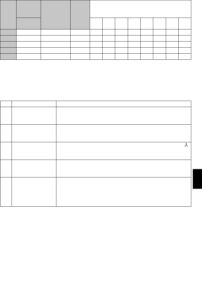
Table 5 Rated Capacities and Outgoing Harmonic Currents for Inverter Drive
Rated
Current
[A]
Fundamental Wave Current Converted from 6.6kV
(No reactor, 100% operation ratio)
Applied
Motor
(kW)
400V
6.6kV
Equivalent of
Fundamental
Wave Current
(mA)
Rated
Capacity
(kVA)
5th 7th 11th 13th 17th 19th 23rd 25th
0.4 0.81 49 0.57 31.85 20.09 4.165 3.773 2.107 1.519 1.274 0.882
0.75 1.37 83 0.97 53.95 34.03 7.055 6.391 3.569 2.573 2.158 1.494
1.5 2.75 167 1.95 108.6 68.47 14.20 12.86 7.181 5.177 4.342 3.006
2.2 3.96 240 2.81 156.0 98.40 20.40 18.48 10.32 7.440 6.240 4.320
3.7 6.50 394 4.61 257.1 161.5 33.49 30.34 16.94 12.21 10.24 7.092
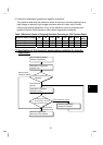
3) Harmonic suppression technique requirement
If the outgoing harmonic current is higher than; maximum value per 1kW (contract
power) × contract power, a harmonic suppression technique is required.
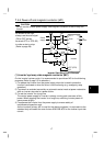
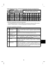
4) Harmonic suppression techniques
No. Item Description
1
Reactor installation
(ACL, DCL)
Install a reactor (ACL) in the AC side of the inverter or a reactor
(DCL) in its DC side or both to suppress outgoing harmonic
currents.
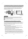
2
Installation of power
factor improving
capacitor
When used with a series reactor, the power factor improving
capacitor has an effect of absorbing harmonic currents.
3
Transformer multi-
phase operation
Use two transformers with a phase angle difference of 30
°
as in
-
∆
,
∆
-
∆
combination to provide an effect corresponding to 12
pulses, reducing low-degree harmonic currents.
4
AC filter A capacitor and a reactor are used together to reduce impedances
at specific frequencies, producing a great effect of absorbing
harmonic currents.
5
Passive filter
(Active filter)
This filter detects the current of a circuit generating a harmonic
current and generates a harmonic current equivalent to a
difference between that current and a fundamental wave current to
suppress a harmonic current at a detection point, providing a great
effect of absorbing harmonic currents.