


157
3
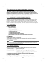
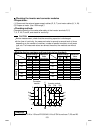
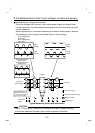
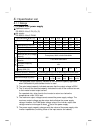
.3.8 Measurement of main circuit voltages, currents and powers
Measurement of voltages and currents
Since the voltages and currents on the inverter power supply and output sides
include harmonics, accurate measurement depends on the instruments used and
circuits measured.
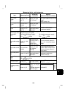
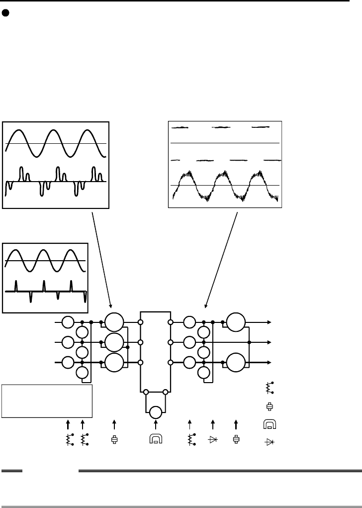
When instruments for commercial frequency are used for measurement, measure
the following circuits using the instruments given on the next page.
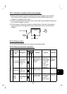
:Moving-iron type
:Electrodynamometer type
:Moving-coil type
:Rectifier type
+-
Ar
As
At
Vr
Vs
Vt
W11
W12
W13
Au
Av
Aw
Vu
Vv
Vw
W21
W22
V
R
S
T
P
U
V
W
N
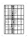
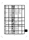
Instrument
t
y
pes
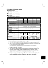
Three-phase 200V
power input
Three-phase 400V
power input
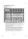
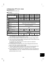
Input
voltage
Input
current
Output
voltage
Output
current
Inverter
3-phase
power supply
To motor
Single-phase 200V
power input
Single-phase 100V
power input
The FR-S520S-0.1K to 1.5K
and FR-S510W-0.1K to
0.75K do not have As, At,
Vt, Vs, W12 and W13.
Typical Measuring Points and Instruments
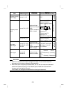
CAUTION
Use FFT (Fast Fourier Transforms) to measure the output voltage accurately.
It cannot be measured accurately with a meter or general instrument.