


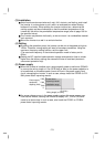
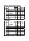
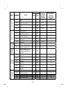
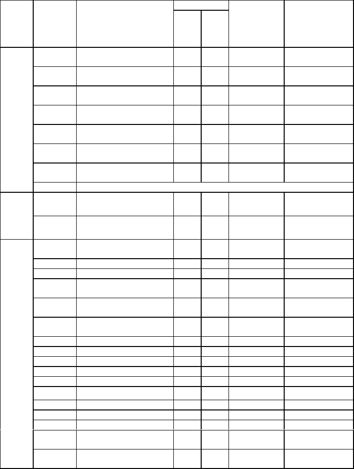
181
Data Code
Func-
tion
Parameter
Number
Name
Read Write
Computer
Link Data
Setting
Increments *
Link Parameter
Extension
Setting
(Data Code
7F/FF)
C1 (900
(901))
FM (AM) terminal
calibration
5C DC
1
C2 (902)
Frequency setting
voltage bias frequency
5E DE 0.01Hz
1
(6C/EC=0)
C3 (902)
Frequency setting
voltage bias
5E DE 0.1%
1
(6C/EC=1)
C4 (903)
Frequency setting
voltage gain
5F DF 0.1%
1
(6C/EC=1)
C5 (904)
Frequency setting current
bias frequency
60 E0 0.01Hz
1
(6C/EC=0)
C6 (904)
Frequency setting current
bias
60 E0 0.1%
1
(6C/EC=1)
C7 (905)
Frequency setting current
gain
61 E1 0.1%
1
(6C/EC=1)
Calibration parameters
C8 (269) Parameter set by manufacturer. Do not set.
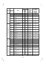
CLr Parameter clear
FC 1
Clear
parameters
ECL Alarm history clear
F4 1
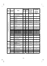
n1 (331)
Communication station
number
1F 9F 1 3
n2 (332) Communication speed 20 A0 1 3
n3 (333) Stop bit length 21 A1 1 3
n4 (334)
Parity check
presence/absence
22 A2 1 3
n5 (335)
Number of
communication retries
23 A3 1 3
n6 (336)
Communication check
time interval
24 A4 0.1s 3
n7 (337) Wait time setting 25 A5 1 3
n8 (338) Operation command write 26 A6 1 3
n9 (339) Speed command write 27 A7 1 3
n10 (340) Link start mode selection 28 A8 1 3
n11 (341) CR/LF selection 29 A9 1 3
n12 (342)
E
2
PROM write selection
2A AA 1 3
n13 (145) PU display language 2D AD 1 1
n14 (990) PU buzzer sound control 5A DA 1 9
n15 (991) PU contrast adjustment 5B DB 1 9
n16 (992)
PU main display screen
data selection
5C DC 1 9
Communication parameters
n17 (993)
PU disconnection
detection/PU setting lock
5D DD 1 9
The parameter numbers within parentheses are those for use of the parameter unit
(FR-PU04).
* Though parameter setting by RS-485 communication can be made in the setting
increments indicated in the table, note that the valid setting increments are as
indicated in the parameter list (page 46).