


C. Traps and MIBs
C-8
August 2002 4200-A2-GB20-00
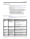
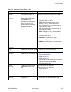
MIB II (RFC 2863)
The objects defined by MIB II (RFC 2863) are organized into the following groups:
Interfaces Group (see
Evolution of the Interfaces Group of MIB II (RFC 2863)
)
MIB II (RFC 2863) Extension to the Interface Table
MIB II (RFC 2863) Interface Stack Group
MIB II (RFC 2863) Interface Test Table
MIB II (RFC 2863) ifTestEntry Table
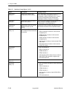
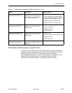
Evolution of the Interfaces Group of MIB II (RFC 2863)
The evolution of the Interfaces Group of MIB II (RFC 2863 converted to SNMP v1)
consists of an object indicating the number of interfaces supported by the
GranDSLAM 4200 and an interface table containing an entry for each interface.
There will be interface table entries for an uplink interface, each of the ATM cell
interfaces, an AAL5 interface, a DSL interface, and an RFC 1483 virtual interface
(see Table C-3, Interfaces Group Objects, for the objects supported).
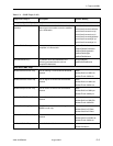
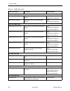
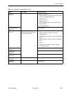
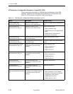
sysLocation
(system 6)
Provides the physical location
for the node.
ASCII character string (32 characters), as set by the user:
badValue(3) – Field length exceeded.
sysServices
(system 7)
Theset of services potentially
offered by the unit. The value is
a sum which initially takes the
value of zero. For each OSI
layer (L) that this node
performs tarnsactions for, 2
raised to L-1 is added to the
sum.
Layer 1: Layer 1 functionality (physical) value is
2^(1-1)=2^0=1. The sum is 1.
Layer2 – Layer 2 functionality (datalink/subnetwork)
value is 2^(2-1)=2^1=2. The sum is 3.
Layer3 – Layer 3 functionality (internet) value is
2^(3-1)=2^2=4. The sum is 7.
Layer4 – Layer 4 functionality (end-to-end) value is
2^(4-1)=2^3=8. The sum is 15.
Layer7 – Layer 7 functionality (application) value is
2^(7-1)=2^6=64. The sum is 79.
Table C-2. System Group Objects (2 of 2)
Object Description Setting/Contents