


RuggedRouter® User Guide
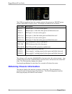
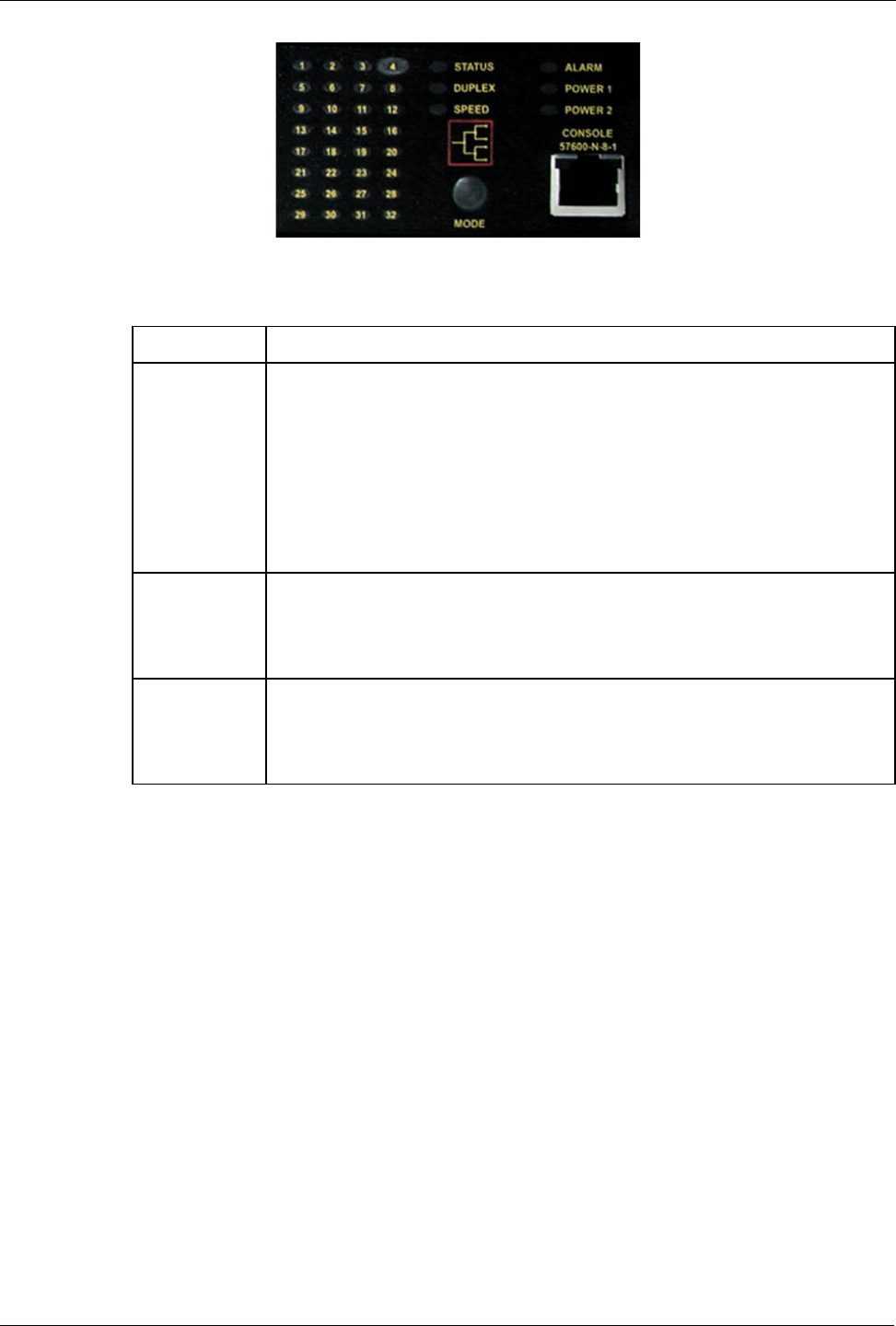
The LEDs are organized into three primary groups; the port group, GPS/PPP group
and the Alarm/Power Supply group. The display possibilities are as follows:
LED Name Description
LED 1-4 Ethernet port 1-4 is active when green
LED 5-8 Ethernet port 1-4 has link when green and failed when red
LED 9-12 WAN port 1-4 is active when green
LED 13-16 WAN port 1-4 has link when green and failed when red
LED 17-20 WAN port 5-8 is active when green
LED 21-24 WAN port 5-8 has link when green and failed when red
PPP-DATA PPP Modem port is active when green
PPP-LINK PPP Modem port has link when green
GPS-LOCK The PTP card GPS system has satellite lock
ALARM A Major Alarm exists when red
POWER 1 Power supply 1 working properly when green and failed when red
POWER 2 Power supply 2 working properly when green and failed when red
Figure 14: Meaning of LEDs
The software will cause the ALARM LED to become active for various reasons. Any
condition that causes the ALARM LED to become active will activate the critical fail
relay. The Web interface displays the alarms.
Pressing the pushbutton for more than five seconds will reboot the router.
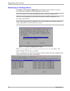
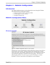
Obtaining Chassis Information
The chassis displays the hardware inventory at boot time. This information is
captured in the /var/log/messages file after boot. The Web Management interface
home page displays the chassis serial number.
34 RuggedCom
Figure 13: LED Status Panel