


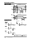
● Parallel interface
[DATA1 to DATA8]
Each of these signals is an 8-bit data signal. It is high
when the signal is logic 1 and low when the signal is
logic 0. DATA1 is the LSB, and DATA8 is the MSB.
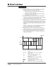
[STROBE]
This is a strobe signal for reading an 8-bit data signal.
Data is read in at the falling or rising edge of the
STROBE signal.
[INITIAL]
This signal initializes the printer to the state in which the
printer starts up when the power is turned on. It is
normally high. When it is set to low, the printer is reset.
When it is set to high again, the printer is initialized.
[AUTO FEED]
If this signal is set to low when #27 CR SETTING is set
to AUTOFEED in the
EXTENDED SETUP MODE, line
feeding is performed when the CR command is executed.
In the HP mode or IBM mode, it is possible to specify
whether to perform line feeding after executing the CR
command by using the software command, regardless of
the settings of this signal and #27 CR SETTING in the
EXTENDED SETUP MODE.
[SELECT IN]
When this signal is set to high, the control code is
validated. Validity of this signal is specified in the
extended setup mode. In the HP mode, this signal setting
is ignored.
7-3
— 7. Interface specifications —
Signal explanations
Input signals to the printer
See page 3-53.
See page 3-29.
See page 3-53.
See page 3-47.
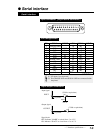
Each signal wire must be 2 meters or less in
length. It is recommended that a twisted pair
of signal and GND wires be used.