


● Serial interface
7-5
— 7. Interface specifications —
Serial interface
Pin configuration
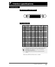
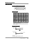
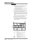
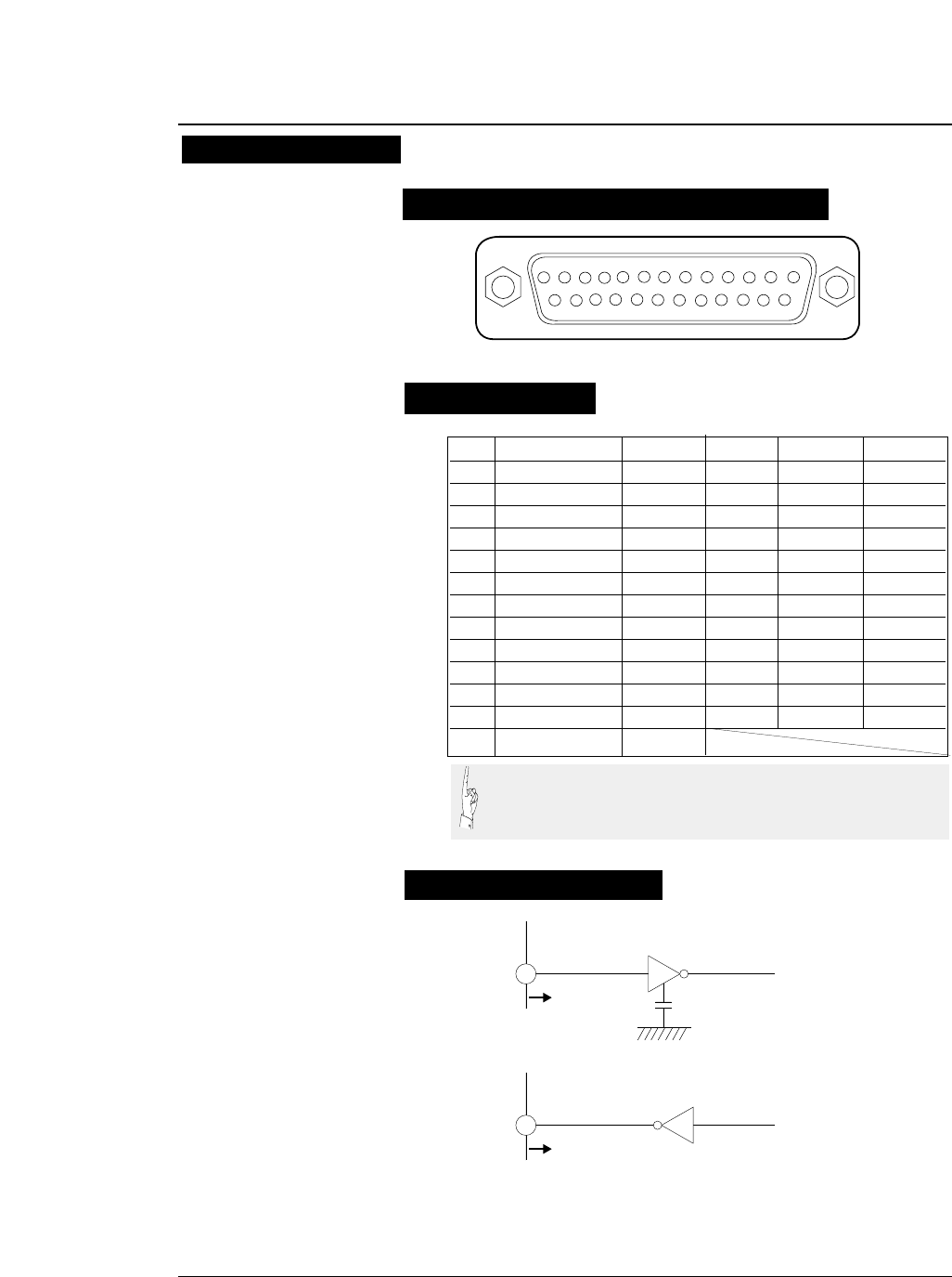
Input connector (25-pin serial connector)
13245678910111213
15 1416171819202122232425
PIN SIGNAL IN/OUT PIN SIGNAL IN/OUT
1 CHASSIS GND 14 NC
2 TXD OUT 15 NC
3 RXD IN 16 NC
4 RTS OUT 17 NC
5 CTS IN 18 NC
6 DSR IN 19 NC
7 SIGNAL GND 20 DTR OUT
8CD IN21NC
9NC 22NC
10 NC 23 NC
11 SRTS OUT 24 NC
12 NC 25 NC
13 NC
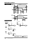
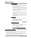
To printer
INPUT
330pF
(75189 or equivalent)
To printer
OUTPUT
(75188 or equivalent)
Signal levels
OFF: Indicates "MARK" at a level from -3 to -15 V.
ON: Indicates "SPACE" at a level from +3 to +15 V.
Input signal
Output signal
Input/output conditions
(1) NC means "not connected".
(2) The CHASSIS GND and SIGNAL GND are connected inside
the printer.