


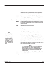
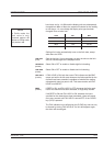
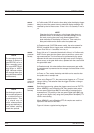
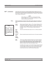
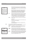
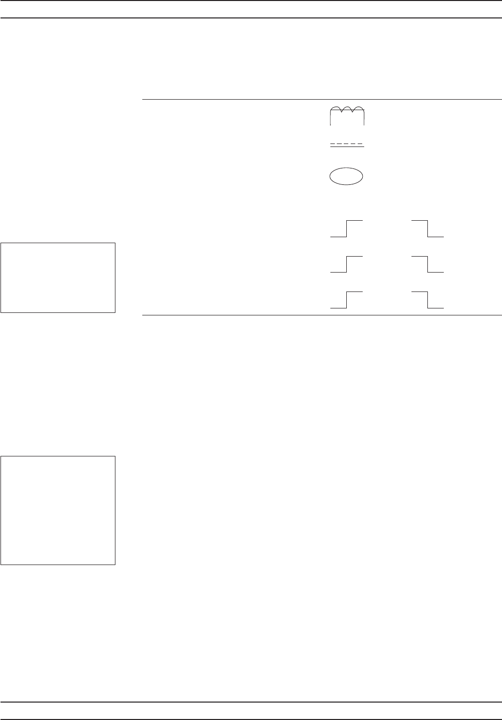
The trigger icons appear as shown in Figure 4-2.
Only when a channel input configuration includes a sensor with a measurement
mode that requires an icon, will an icon be displayed.
Setup This menu is used to set up the trigger conditions for the display channels. In
readout display mode with sensor mode set to custom, the trigger can be set to
display channel 1 and 2 separately, or together as channel 1 & 2.
The channels are triggered simultaneously if the trigger conditions are set to 1 &
2. This guarantees the trigger conditions are the same, and therefore the read
-
ings are taken at the same time. In Readout and Power vs. Time modes, if the
menu is exited with the trigger selection at channel 1 & 2, this setup is used for
trigger control. Otherwise, if the trigger setup display is left with channel 1 or
channel 2 displayed, the individual trigger settings are used for trigger control.
CHANNEL
[TRGMODE]
Select display channel 1 or 2 (or 1&2 when setting trigger condi
-
tions in Readout or Power vs. Time modes).
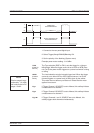
SOURCE
[TRGSRC
GTSRC]
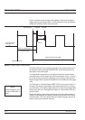
The trigger sources are CONTINUOUS, Internal A, Internal B
(ML2438A only), EXTTTL, or MANUAL . When the trigger source is
set to INT A or INT B (Internal A or B) the power meter triggers on
a rising or falling power level on the associated sensor. See LEVEL
for the setting of the trigger power level.
ML2430A OM 4-17
OPERATION TRIGGER MENU
MOD
MAN
INT
A
INT
A
INT
B
INT
B
TTL TTL
Modulated Average
Continuous
Manual
Rising Edge Falling Edge
External
Internal A
Internal B
Figure 4-2. Trigger Icons
NOTE
Simultaneous trigger
channels guarantee
identical sampling for
both channels, essen
-
tial for accurate ratio
(A/B) measurements.
NOTE
External trigger is only
effective at 800 KHz or
lower.