


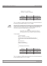

System|Source Sweep|Data Hold can be used to select the way in which data is
plotted. Using Min/Max variation (both minimum and maximum) can be shown on
the display. Using Max effectively provides a peak hold. If the display of swept
power is not what is expected, check the setting of AVERAGE and the DATA
HOLD mode in case it is affecting the data processing.
NOTE
As with other graphic modes, improved speed can be achieved in ATE sys
-
tems by disabling the graphic draw function for the LCD through the menus
using SYSTEM|-more-|-more-|Graphics|CONNECT. Setting CONNECT to
OFF displaces the line-drawing between samples, and improves update
rate. Similarly, for ATE systems, the READOUT should be disabled for fast
-
est throughput as this can all be handled within the controller (PC). Sensor
range hold is not available in this mode of operation as auto ranging is
selected.
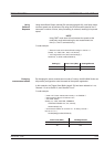
Using the Anritsu
68/69000 Synthesizer
The ML2430A Series can be connected directly to the Anritsu 68/69000-Series
Synthesized Signal Generators (models 68XXXB and 69XXXA) using a special
RS232 cable (Anritsu part number C37399). To use this remote connection, the
System|Setup mode must be set to Source sweep, and the System|Rear
panel|RS232 mode must be set to SOURCE IF. The RS232 mode can also be
changed using the GPIB command RSMODE (page 6-68).
When set up in this manner, all sweep frequency and power parameters will be
communicated from the source to the meter. If the source frequency power level
or the frequency itself is changed, the source sweep display will be updated
where appropriate.
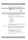
To communicate with an Anritsu 68/69000-series synthesizers, the synthesizer
firmware must be later than the levels shown below for each model:
680xxB - 3.39, 681xxB - 3.44, 682xxB - 2.41, 683xxB - 2.50, 680x5B - 1.26,
681x5B - 1.32, 682x5B - 1.30, 683x5B - 1.34, 690xxA - 1.21, 691xxA - 1.26,
692xxA - 1.26, 693xxA - 1.35, 690x5A - 1.21, 691x5A - 1.24, 692x5A - 1.24,
693x5A - 1.31
Contact your nearest Anritsu Service Center for a firmware upgrade if necessary.
5-13
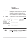
POWER vs.
TIME MODE
The ML2430A Series Power vs. Time mode is a graphical chart display of one of
the display channels, as selected in the SYSTEM|PWRvsTIME menu. The trig
-
gering setup is as set for Readout mode operation.
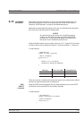
Power vs. Time mode provides a chart display on a timed basis where the x-axis
of the graph is defined in units of time. The user specifies the sweep period and,
within this sweep period, each pixel depicts all the measurements taken within a
200th of the sweep period.
5-18 ML2430A OM
POWER vs.
TIME MODE PROCEDURES