


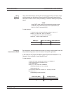

The data can be displayed as a maximum value only, a minimum value only, max
-
imum and minimum values, the average of all the readings during the time slot
period, or the latest measured value. These display modes are selected in the
SYSTEM|PwrVsTime menu, DATA HOLD representation. Measurement setup,
i.e., trigger, etc., is selected the same way as in Readout mode. The minimum
sweep time is 1 minute, and the maximum sweep time is 24 hours.
5-14
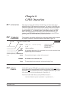
USER CAL
FACTORS
All MA24XXA Power Sensors have an internal EEPROM containing correction
and calibration factors programmed into the sensor at the factory. This “cal factor”
data is used when the power meter is set up to use frequency or volts per GHz
calibration factors. The correction is in linearity (across the dynamic range) and
sensitivity (across frequency).
The ML2430A Series has the capability to define sets of calibration factor data
and store them in the sensor. A user-defined cal factor table can be used on its
own, or in conjunction with the factory-defined cal factor table. Linearity correction
is not affected provided the meter cal factor frequency is set correctly.
Depending on the amount of factory calibration data stored in the sensor, there
can be up to 10 user-defined cal factor tables. A “user” cal factor table consists of
up to 90 frequency/cal factor data pairs for sensors up to 40 GHz or 110 fre-
quency/cal factor data pairs for sensors up to 50 GHz, plus a 7-character identity
text string. User cal factor tables are fully interpolated, and can be used to apply
correction for attenuators placed in front of the sensor. In this situation, determine
the attenuation factors and use them in addition to the Factory cal factors. The
number of frequency/cal factor data pairs in the factory defined table depends on
the sensor being used.
The cal factor tables for a particular sensor are not maintained by the meter, but
are held in the sensor. This means that when moving a sensor (perhaps with an
associated attenuator or calibration record) from one meter to another, the cali
-
bration stays valid. It is not necessary to re-setup the new meter.
The first time a sensor is used with the ML2430A Series, a slight delay may be
experienced when the sensor is first plugged in. This is caused by the firmware
preparing the sensor to accept user cal factor tables. After first initialization, user
cal factor tables will have only a single entry at 50 MHz, 100%.
PROCEDURES USER CAL FACTORS
ML2430A OM 5-19
NOTE
This feature is also
available when using
Anritsu MA4700A/
MA4600A sensors with
the Anritsu MA2499B
Sensor Adapter. Since
the MA4700A/
MA4600A sensors do
not contain an
EEPROM, the user cal
factors are storedin the
MA2499B adapter
EEPROM.
NOTE
A * in the displayed sta
-
tus box by the Cal Fac
-
tor indicator, signifies
User Cal Factors are
active.
User Cal Factors are
maintained in the sen
-
sor.