


Page 28
724-746-5500 | blackbox.com
LB308A
Chapter 3: Installation
Ethernet Extender Switch.
1
2
5
3
4
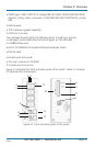
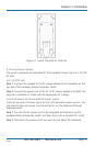
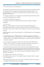
Figure 2-3. Power connectors on the switch.
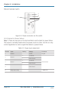
3.3.3 Alarms for Power Failure
Step 1: There are two pins on the terminal block used to detect a power failure.
The output is normally closed when the power source is active. Use this as a dry-
contact application to send a signal that detects a power failure.
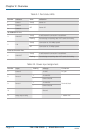
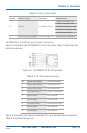
Table 3-1. Power input assignment.
Number Input Polarity Voltage Connector
1 Power 3 12 VDC DC jack
2 Power 2
+ 12–48 VDC
Terminal block
- Power Ground
3 Power 1
+ 12–48 VDC
- Power Ground
4 Earth Ground
5 Relay output rating 1 A @24 VDC