●
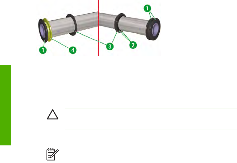
If the tension bar is going to be installed in the slack area of the media, use one or more tension bars
(3) to create a total length that is equivalent to half the width of the media and do not install the flanges
(1), ESD flange (4) and the take-up flanges (3) and their associated fixing rings (2).
●
If the tension bar is going to be installed in the tension bar guides, use the required tension bars to
create a total length that is equivalent to the width of the printer, at the left hand end install one standard
flange (1) and one ESD flange (4) , slide the take-up flanges (3) and their associated fixing rings (2)
onto the tension bar, and install two standard flanges (1) at the right hand end.
CAUTION You must always clean the fixing ring and tension bar using alcohol to remove
any dirt because this could cause the fixing ring to become displaced during take-up,
resulting in the media being wound unevenly.
●
Install the flanges at each end of the tension bar. When you insert the tension bar into the flange, align
the cutouts in the flange with the screw heads in the tension bar.
NOTE For vinyl chloride (PVC) media assemble the tension bar in the same way as for
the feed side (no flanges, take-up flanges, or fixing rings).
Use media tube flanges
You use the media tube flanges to take-up media such as vinyl chloride (PVC) and FF which are both
susceptible to weaving. In some cases special spacers are required to install the media tube flanges. These
special spaces are needed when the media tube cannot be fully engaged with the end flanges because
the inside diameter of the tube is too small.
The following flanges are supplied:
●
3 x rubber spacer A (1)
●
3 x rubber spacer B (2)
●
1 x rubber spacer C (3)
60 Chapter 2 How do I perform basic media operations? ENWW
How do I perform basic media
o
p
erations?


