


200 Configuring APs
NN47250-500 (320657-F Version 02.01)
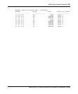
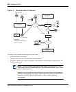
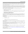
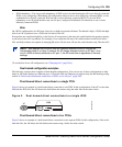
Figure 1. Example Nortel network
To configure APs, perform the following tasks, in this order:
• Specify the country of operation.
• Configure AP access ports, AP connections, and dual homing.
• If required, configure radio-specific parameters, which include the channel number, transmit power, and
external antenna model.
Note. You do not need to set channels and power if you use Auto-RF to set
these values. You do not need to specify an external antenna model unless a radio
uses an external antenna.
However, if you do install an external antenna, you must ensure that the external
antenna model parameter you specify exactly matches the external antenna that is
attached to the AP’s external antenna port, in order to meet regulatory
requirements.
2330
Router
Router
Wired
authentication
client
System IP address
10.10.10.4
2330
Port
1
Port
2
Port
4
WSS1
10.10.40.19/24
10.10.20.19/24
10.10.30.19/24
RADIUS
servers
10.10.70.20
10.10.70.40
10.10.60.18/24
10.10.60.19/24
WMS
Port
3
2330
Layer 2
2330
System IP address
10.10.40.4
WSS2
Layer 2
2330
10.10.10.19/24
System IP address
10.10.50.4
WSS3
Port
5
VLANs on WSS1
VLAN 2 mgmt, port 5, 10.10.10.4/24
VLAN 4 blue, port 5, tag 20, 10.10.20.2/24
VLAN 3 red, port 5, tag 30
Layer 2
serial-id 0322199998
serial-id 0322199999
serial-id 0322199997
serial-id 0322199996
serial-id 0322199995
10.10.50.19/24
external antenna
model 5303