


How to Configure a Virtual Tie Line 85
Max = 6) sequence. Entry 101 watches for the 2-digit sequence 63
followed by a 4-digit extension and specifies route 523 whenever a user
dials such a 6-digit sequence. The choice of route numbers is made by the
person configuring the dial plans for the sites.
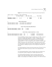
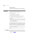
Two DestinationRoute Create commands create routes 522 and 523. The
Description field contains any text you want to use to describe each
route.
Two DestinationRouteEntry Create commands specify the extension list
for routes 522 and 523. Extension list *0006 is the default extension list
for VTLs.
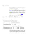
For each DestinationRoute, two DestinationRouteOperation Create
commands perform two functions:
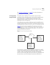
■ The stripLead command removes the two digits (62 or 63) leaving the
4-digit extension the user dialed.
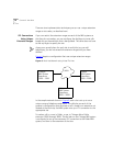
■ The prepend command adds the IP Address of the destination NBX
system to the extension that the user dialed. In this example, the IP
address for Atlanta is 192.169.25.100 and for Dallas, the IP address is
192.168.35.100. In the dial plan, you must use an asterisk (*) instead
of a period (.) to separate the fields within the IP address, and to
separate the IP address from the destination extension.
Updating the
Extension List
The final step in activating the virtual tie lines is to add the VTL extensions
to the appropriate extension list (*0006).
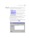
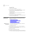
To update the extension list:
1 In the NBX NetSet - Main Menu window, click Dial Plan.
2 Click the Extension Lists tab.
3 Select the Virtual Tie Lines extension list (*0006).
4 Click Modify.
5 In Extensions not in List, scroll down until you see the first VTL item.
The number of VTL items depends on the VTL license you have.
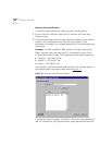
Each VTL item has (VTL) at the beginning of the line, followed by the
name of the virtual tie line.
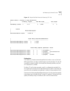
Table 19
describes the VTL extension ranges.
6 Select the first VTL, and click << to move the VTL to Extensions in List.