


4-10 Agilent B2200 User’s Guide, Edition 2
Programming
Programming Examples
Using Bias Mode
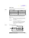
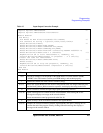
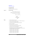
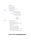
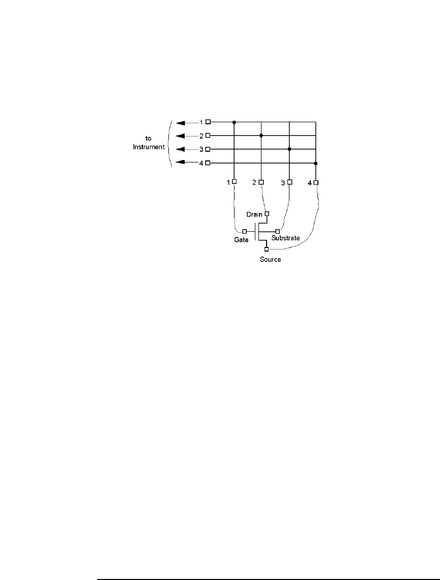
The following example uses the bias mode.
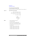
Figure 4-3 Bias Mode Example
Setup: • Channel configuration mode: Auto
• Connection rule: Single. Multiple connection is available for the bias port.
• Connection sequence: Break_Before_Make
• Used module: All switch modules installed in the mainframe.
• Bias port: AUX Input 10
• Bias enabled output port: All output ports
• Connection paths (connected when the bias mode is ON):
from bias port to all bias enabled output ports
• Connection paths (connected by the :ROUT:CLOS command):
The following output ports will be disconnected from the bias port, and the
following input-output connections will be made.
from SMU1 to Output 1 (channel list 00101)
from SMU2 to Output 2 (channel list 00202)
from SMU3 to Output 3 (channel list 00303)
from SMU4 to Output 4 (channel list 00404)