


Agilent B2200 User’s Guide, Edition 2 2-23
Installation
Measurement Cable Length
Measurement Cable Length
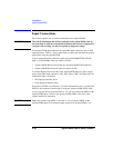
This section describes how to calculate the total guard capacitance when using an
SMU (source monitor unit). When using an SMU, the length of measurement cables
is limited by the guard capacitance of the cables. The guard capacitance means the
capacitance between the signal line (Force or Sense) and the Guard line.
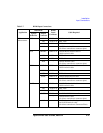
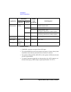
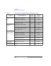
Table 2-8 lists the guard capacitance for each element of the Agilent B2200’s
measurement environment.
When using the 4155/4156/4142B/E5260/E5270, the maximum limit of the guard
capacitance is approximately 900 pF. So, you add the following and total must be
less than 900 pF:
• Guard capacitance of cable from SMU to B2200 inputs.
• Guard capacitance of mainframe and modules.
• Guard capacitance of cable from B2200 outputs.
• Guard capacitance of cable from connector plate to DUT.
• Other capacitances, such as for probe card.
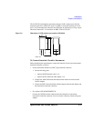
The following is an example to calculate the guard capacitance of a measurement
environment:
Installed Plug-in cards: Four B2210As (145 pF + 8 pF × 3)
Input Cable: 16494A-003 (75 pF)
Output Cable: 16494A-001 (130 pF)
Cable from Connector
Plate to DUT: 8121-1191, 1 m (130 pF)
Probe Card: Guard Capacitance approximately 10 pF (example)
In this environment, the total guard capacitance (Cg-total) is as follows.
Cg-total = 145+(8×3)+75+130+130+10 pF = 514 pF < 900 pF
Even if you use other instruments, you can use the table for reference about the
measurement cable length and capacitance.