


1-4 Agilent B2200 User’s Guide, Edition 2
Introduction
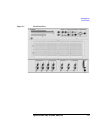
Front Panel
Front Panel
The Agilent B2200 series provides the front panel keys, the LCD, and the LED
matrix display for the status monitor and connection setup.
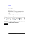
• Line switch
Used to turn the Agilent B2200 on or off.
•LCD
Used to monitor the status and set the connection. See Chapter 3 for the details.
• Front panel keys
Used to set the Agilent B2200. See Chapter 3 for the details.
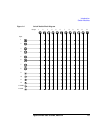
• LED matrix display
Displays the status of the matrix switches. Also used to set the matrix connection
with the light pen.
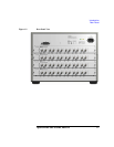
• SMU Input
Inputs for the source monitor unit (SMU). Eight input ports. Up to four kelvin
inputs are available. Triaxial BNC connector.
• AUX Input
Multipurpose inputs. Six input ports. Coaxial BNC connector. CMH and CML
terminals are the input ports for the capacitance measurement.
The input port 12 (AUX Input 12) is the default ground input port. If you assign
the port as the ground input port, this ground port will be internally connected to
the ground when the ground mode is set to ON. In this case, open this connector.
•Light Pen
Connector for the Agilent 16443A Light pen. Used to set the matrix connection
with the LED matrix display.
CAUTION For the SMU Input terminals, the maximum measurement voltage/current/voltage
between terminals are ±200 V/1 A/300 V, respectively. And for the AUX Input
terminals, they are ±100 V/0.5 A/100 V.
Do not apply an input signal over these limits to the input terminals. If you do, the
Agilent B2200 will be damaged. If you use a bias source that has current limit
capability, set the bias source current limit.