


Agilent B2200 User’s Guide, Edition 2 2-15
Installation
Output Connections
To Make Interlock Circuit
The interlock circuit is to prevent electric shock when touching measurement
terminals. You must install an interlock circuit on shielding box to prevent
dangerous voltages when door of the shielding box is open.
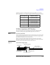
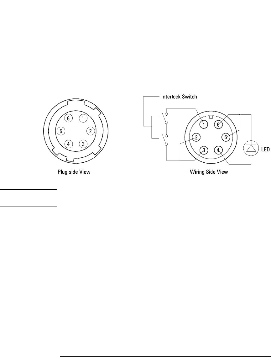
Figure 2-3 shows the pin assignments of the interlock connector.
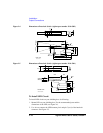
Figure 2-3 Interlock Connector Pin Assignments
WARNING Dangerous voltages of up to the maximum voltage of SMUs may be present at
force, guard, and sense terminals when the interlock terminals are shorted.
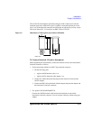
To Install Interlock Circuit
Install the interlock circuit as follows.
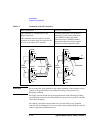
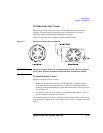
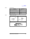
1. Mount two mechanical switches on your shielding box, so that the switches
close when the door of the shielding box is closed, and open when the door is
opened. For the recommended parts and the dimensions of the switch, see Figure
2-4 and Figure 2-5.
2. Use wire to connect the two switches in series between pin number 1 and 2 (or
3) of the interlock connector. See Figure 2-3.
For example, Agilent 4155/4156 is connected to the interlock circuit, it cannot force
more than ±40 V when the door is open. When door is closed, it can force more than
±40 V.