


1-8 Agilent B2200 User’s Guide, Edition 2
Introduction
Switch Modules
Switch Modules
The Agilent B2200A and B2201A support the dedicated switch module, Agilent
B2210A and B2211A, respectively.
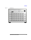
By installing the modules, the module inputs will be connected internally to the
front panel input connectors. And 12 output connectors will face the rear panel. The
type of the output connectors is the triaxial BNC. Up to six kelvin outputs are
available.
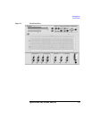
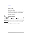
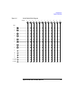
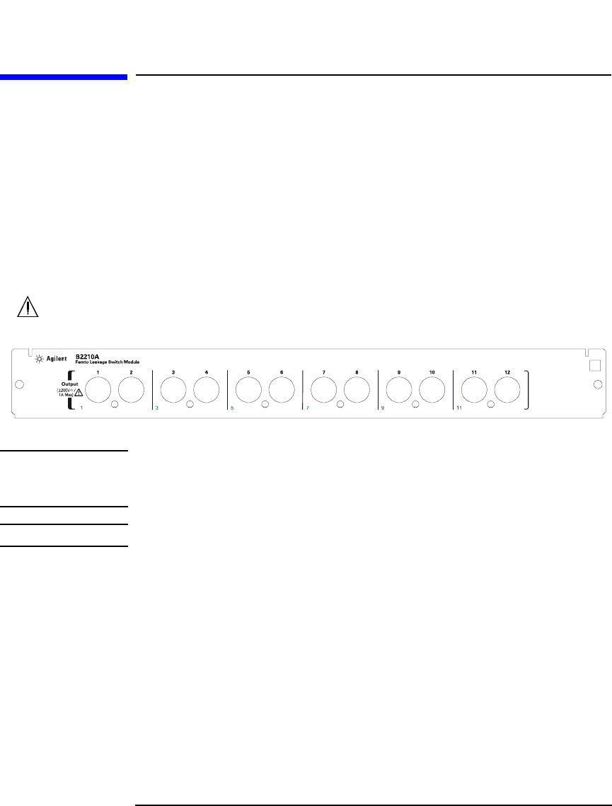
Image of the output terminals and the block diagram of the switch module are
shown in Figure 1-3 and Figure 1-4.
Figure 1-3 Switch Module Output Terminals
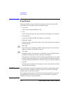
WARNING Do not touch the force and guard terminals of the output connectors while the
Agilent B2200 is turned on. Dangerous voltages up to the maximum input
voltage may be present at the output connectors.
NOTE Mixed configuration of the switch modules is not supported.