


Agilent B2200 User’s Guide, Edition 2 2-13
Installation
Output Connections
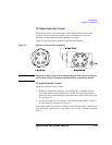
For Kelvin connection, use Kelvin triaxial cable listed in Table 2-3. To make a
Kelvin output port (1, 3, 5, 7, 9 and 11), couple two E5252A output ports as follows:
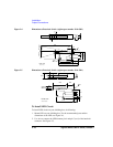
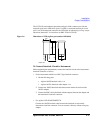
To Make Connections to DUT Interface
This section describes for the connections between the DUT interface and the
connectors connected to the Agilent B2200 output cables. See Table 2-4.
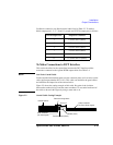
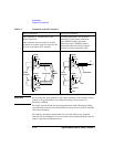
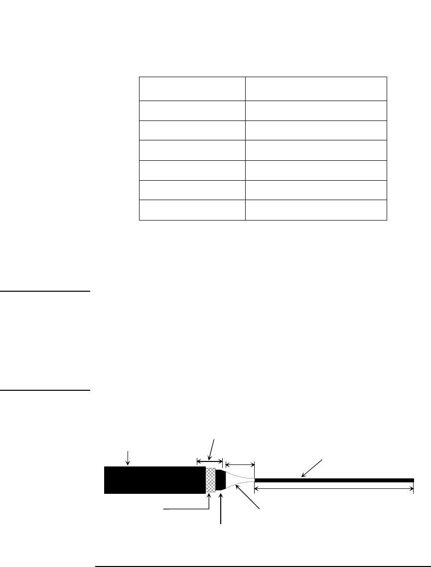
NOTE Low-Noise Coaxial Cable
For the extended measurement paths over the connector plate, use low-noise coaxial
cable (Agilent part number 8121-1191). This cable can maximize the guard effects
and minimize the impression of the external noise.
Figure 2-2 shows the cutting example of this cable. Key point is the isolation
between the conductive layer and the center conductor. So, cut and trim the end of
the cable as shown in this figure by using a cutter and so on.
Figure 2-2 Coaxial Cable Cutting Example
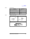
Kelvin Output Port Output Port Number
1 1 (Force) and 2 (Sense)
3 3 (Force) and 4 (Sense)
5 5 (Force) and 6 (Sense)
7 7 (Force) and 8 (Sense)
9 9 (Force) and 10 (Sense)
11 11 (Force) and 12 (Sense)
Insulator (black)
Outer conductor
(for Guard signal)
Insulator (clear)
Conductive layer (black)
Center conductor
(for Force/Sense signal)
approx. 10 to 15 mm
min 2 mm
Cover here using sleeve