


Agilent B2200 User’s Guide, Edition 2 2-11
Installation
Output Connections
Output Connections
This section describes how to connect the Agilent B2200 outputs to prober,
connector plate, test fixture, and so on (DUT interface).
• “Output Connectors”
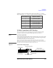
• “Connector Plates”
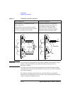
• “To Make Connections to DUT Interface”
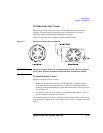
• “To Make Interlock Circuit”
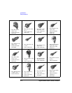
• “To Mount Connectors”
NOTE Output Connections
If you do not use the connector plate for the connection between the output and the
DUT interface, see “To Mount Connectors” on page 2-18.
WARNING Turn off the Agilent B2200 and all instruments connected. And do not turn
them on until the connection described in this section is completed. If you
ignore this warning, you may be exposed to dangerous voltage.
Output Connectors
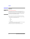
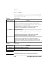
The Agilent B2200 output connectors are the triaxial BNC connector. The input
signals appears at the output as shown in Figure 2-1 when input-output switching
path is made. Figure 2-1 shows signals appear on the output connectors with
non-Kelvin connection. If you make Kelvin connection, the signal of the even
output connectors is Sense, not Force.
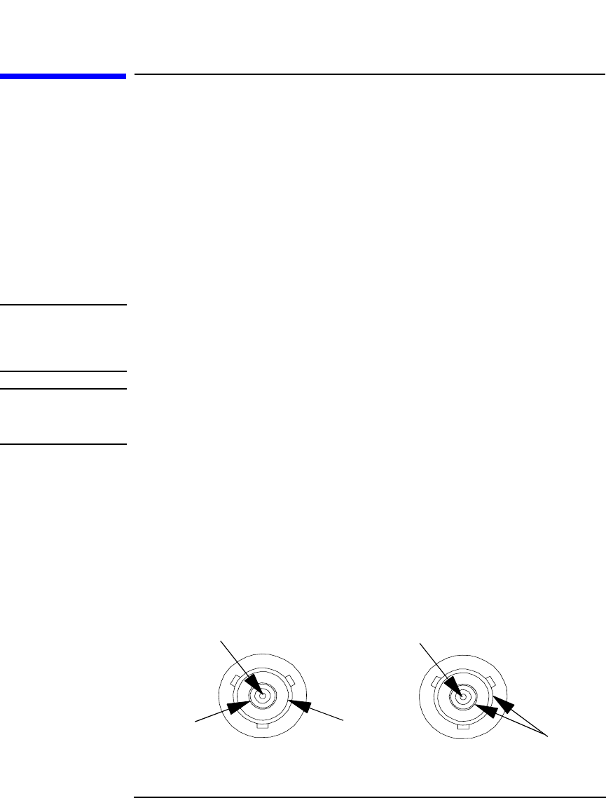
Figure 2-1 Output Connector and Output Signal
(a) When SMU is connected
(b) When AUX is connected
Signal (force)
GND
Signal (force)
GND
GUARD