


Agilent B2200 User’s Guide, Edition 2 2-17
Installation
Output Connections
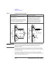
The 4155/4156 semiconductor parameter analyzer's Intlk connector provides the
interlock signal and a LED drive signal. If a LED is connected between pin 4 and
pin 5 (or 6) of the interlock connector, the LED lights to indicate high voltage output
when more than ±40 V is forced from an SMU in the 4155/4156.
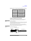
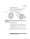
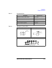
Figure 2-6 Dimensions of LED (Agilent part number 1450-0641)
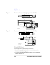
To Connect Interlock Circuit to Instrument
Before beginning the measurement, connect the interlock circuit to the instrument’s
interlock connector as follows.
• For the instruments which has a BNC-Type interlock connector:
1. Get the following parts.
• Agilent 16493J Interlock cable, 1 ea.
• Agilent 16435A Interlock cable adapter, 1 ea.
2. Connect the 16493J interlock cable between the interlock circuit and the
16435A adapter.
3. Connect the BNC cable (furnished with the adapter) between the adapter and
the instrument’s interlock connector.
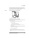
• For Agilent 4155/4156/E5260/E5270:
Connect the 16493J interlock cable between the interlock circuit and the
instrument’s interlock connector. You can connect it directly without using any
adapter.
6
10
11
5
5.6
5
Cathode(-)
Anode(+)
Units: mm