


Agilent B2200 User’s Guide, Edition 2 4-21
Programming
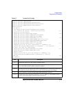
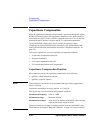
Capacitance Compensation
Required Conditions
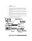
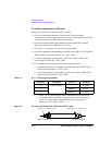
The following conditions must be satisfied to use the capacitance compensation
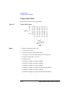
function. For the instrument connections, see Figure 4-6.
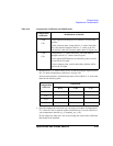
• Setting of the 4284A
• Option required: 4284A-006
• Range of the measurement frequency: 1 kHz to 1 MHz
• Measurement function: Cp-G
• Connection to Agilent B2200
Use the Agilent 16494F CMU cable or the Agilent 16048D/E test leads to
connect between the Agilent 4284A and the Agilent B2200 inputs.
If the 16048D/E is used, the BNC-T adapters (2 ea., Agilent part number
1250-2405 for each) are required to connect between the Hc and Hp
terminals and between the Lc and Lp terminals.
• Calibration
Perform the 4284A open calibration at the end of the measurement paths in
front of the B2200 inputs. If you also perform the short calibration
(optional), prepare the BNC thru adapter (Agilent part number 1250-0080,
1 ea.).
• Total cable length of both Hc-Hp side and Lc-Lp side must be the same.
• Agilent B2200 input ports
AUX Input 13 (CMH, for 4284A Hc-Hp) and 14 (CML, for 4284A Lc-Lp)
• Connection from the Agilent B2200 outputs to the connector plate or the Agilent
B2220A probe card interface
Use the Agilent 16494A triaxial cable or Agilent 16494B/C Kelvin triaxial
cable.
• Ahead of the connector plate
Recommended cable: Agilent part number 8121-1191 Triaxial cable
You can also use another type of triaxial cable, coaxial cable, or combination of
these.
To approximate the capacitance/conductance of the DUT, you need to obtain the
appropriate compensation coefficients for your measurement environment, and
create your compensation data file. See Figure 4-6.