


1-14 Agilent B2200 User’s Guide, Edition 2
Introduction
Specifications
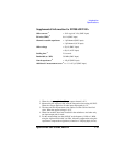
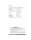
Supplemental Information for B2201A/B2211A
Offset current
1
< 50 fA (SMU input)
IM noise (RMS)
2
5 fA (SMU input)
Channel crosstalk capacitance < 0.5 pF/channel (SMU input)
< 3 pF/channel (AUX input)
Offset voltage < 80 µV (SMU input)
< 100 µV (AUX input)
Settling time
3
2.0 seconds
Bandwidth (at -3dB) 30 MHz (SMU input)
Guard capacitance
4
< 145 pF (SMU input)
Additional C measurement error
5
< ± 1 % + 0.2 pF (SMU input)
1. When the voltage applied to all input-output paths is 0 V.
2. Measured by the Agilent 4156C with the integration time setting 100 PLC.
When the voltage applied to all other input-output paths is 0 V.
3. The time until the measurement value settles to within 300 fA of the final
value. When the applied voltage is 10 V.
4. When four modules have been installed in the mainframe. And when only
one input-output path is made.
5. For the measurement less than 1000 pF at the frequency 1 kHz to 1 MHz,
using the Agilent 4284A with 3 m cable. After the compensation using the
capacitance compensation algorithm (a function of VXIplug&play driver).