


2-16 Agilent B2200 User’s Guide, Edition 2
Installation
Output Connections
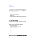
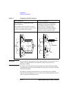
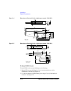
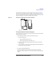
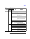
Figure 2-4 Dimensions of Interlock Switch (Agilent part number 3101-0302)
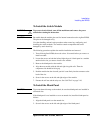
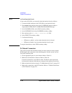
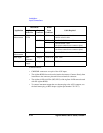
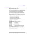
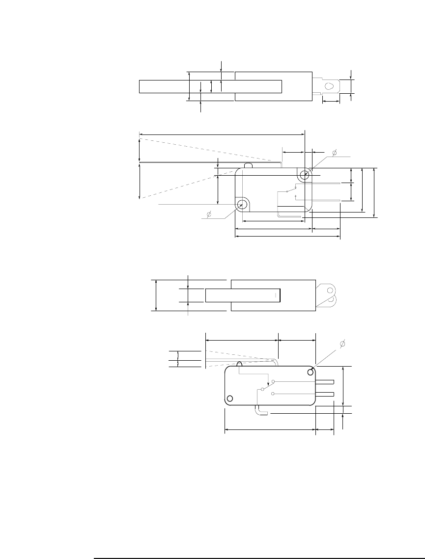
Figure 2-5 Dimensions of Interlock Switch (Agilent part number 3101-3241)
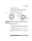
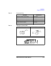
To Install LED Circuit
To install LED circuit on your shielding box, do following:
1. Mount LED on your shielding box. For the recommended parts and the
dimensions of the LED, see Figure 2-6.
2. Use wire to connect the LED between pin 4 and pin 5 (or 6) of the interlock
connector. See Figure 2-3.
3.1
Switch on
59.4
8.1
10
UGI01011,85x60
Units: mm
NC
NO
COM
6.35
22.2
27.8
37.8
2.8
6.5
5.5
15.9
18.8
4.75
10.3
4.3
2.8
2.8
Switch off
Max 9
15.2
10.3
2.8
3.1
3.1
Switch off
Switch on
27.5
10.9
15.9
3.4
27.8 6.8
10.2 4.3
3.2
2.0
UGI01012,85x60
Units: mm