


2-12 Agilent B2200 User’s Guide, Edition 2
Installation
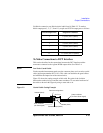
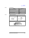
Output Connections
Connector Plates
Connector plates (Table 2-2) are used for the connection between the Agilent B2200
outputs and the DUT interface (prober and so on). To connect to the connector plate,
use the cable shown in Table 2-3.
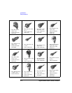
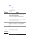
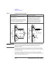
Table 2-2 Connector Plate
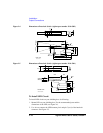
Table 2-3 Output Cable
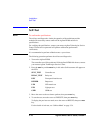
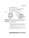
NOTE Installing Connector Plate
To install the connector plate, refer to Agilent 16495 Installation Guide.
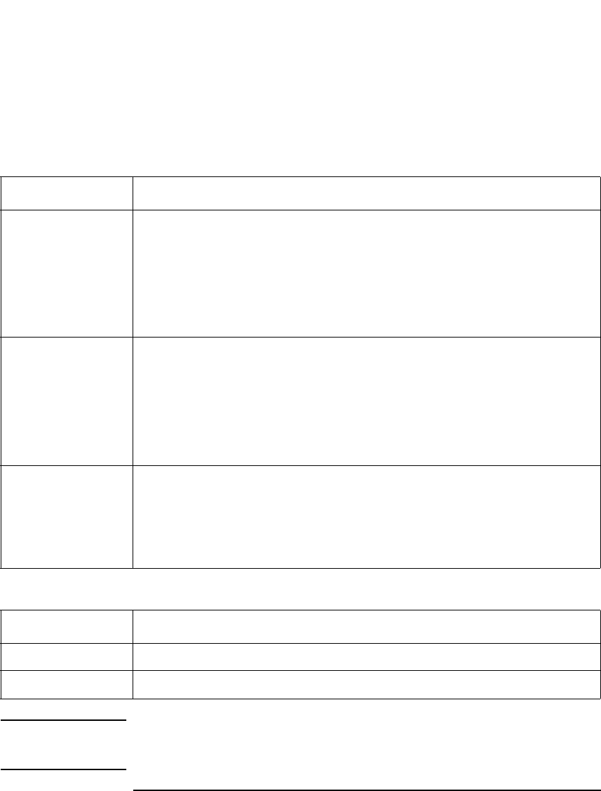
Agilent Model No. Description
16495F Half size connector plate
16495F-001 has 12 triaxial through connectors (female to female), an Intlk
connector, and a GNDU connector (triaxial through, female to female). The back
of the Intlk connector is designed for soldering.
16495F-002 has 12 triaxial connectors, an Intlk connector, and a GNDU
connector. The back of each connector is designed for soldering.
16495G Full size connector plate
16495G-001 has 24 triaxial through connectors (female to female), an Intlk
connector, and a GNDU connector (triaxial through, female to female). The back
of the Intlk connector is designed for soldering.
16495G-002 has 24 triaxial connectors, an Intlk connector, and a GNDU
connector. The back of each connector is designed for soldering.
16495E Blank plate
This plate is used to cover openings when you made too big openings for
mounting the connector plate. You will use this plate to cover openings if you
mount the half size connector plate in openings made for the full size connector
plate.
Agilent Model No. Description
16494A Triaxial cable (for non-Kelvin connection)
16494B Kelvin Triaxial cable (for Kelvin connection)