


Agilent B2200 User’s Guide, Edition 2 4-25
Programming
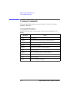
Capacitance Compensation
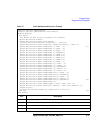
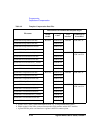
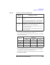
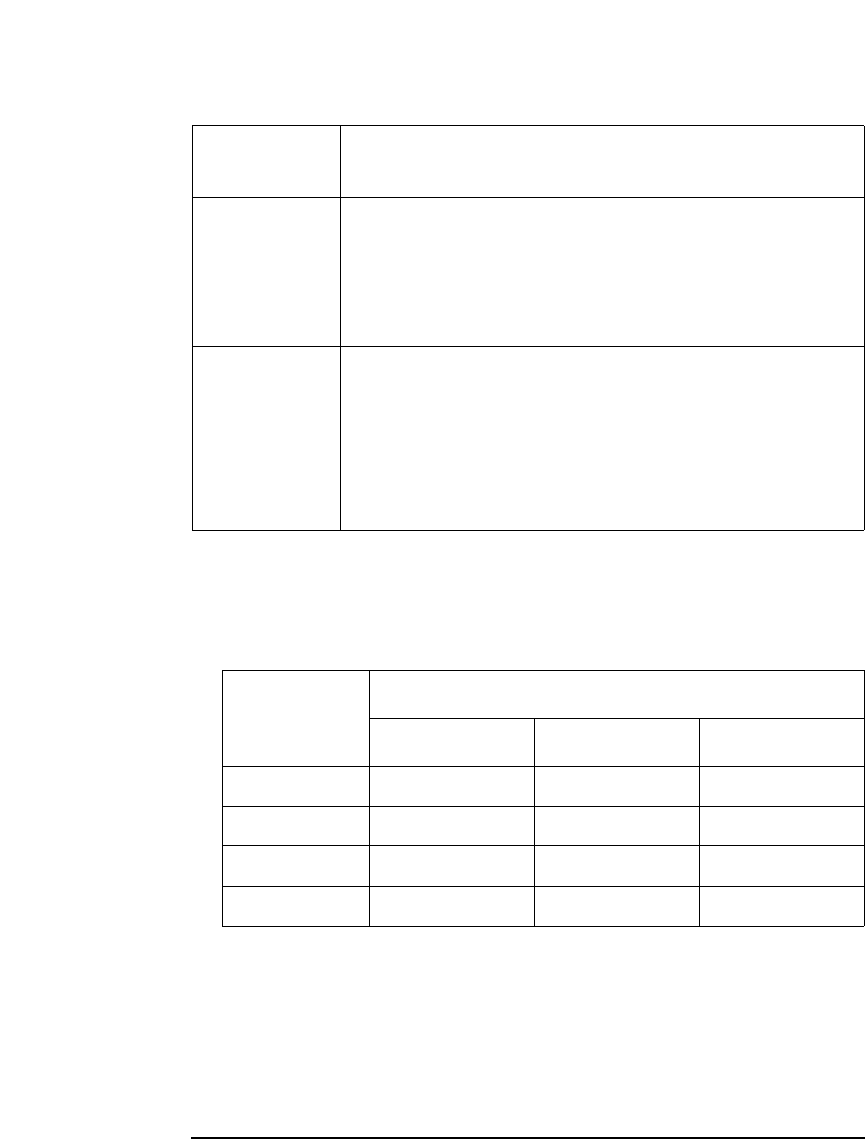
Table 4-10 Compensation Coefficients and Modifications
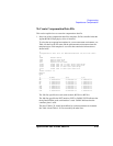
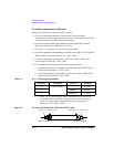
2. Measure the R, L, C values of the C2x or C3x path by using the Agilent 4284A.
See “To obtain compensation coefficients” on page 4-26.
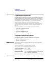
After the measurements, calculate the per meter value of the R, L, C, and record
them into the following table.
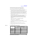
3. Open the template file selected at step 1 by using a text editor. Exchange the R,
L, C values of C2x/C3x with the values recorded at step 2. And save the file as
your compensation data file (e.g. C:\temp\my_env_1.txt).
Do not change any other lines. Also do not change the value for the coefficients
that should not be modified.
Compensation
coefficients
Modifications of data file
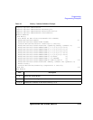
C2H
C2L
For the Agilent B2220A probe card interface, do not modify
the lines.
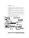
For the connector plate, change the R, L, C values in the lines.
The value must be changed to the R, L, C values of the C2x
path (triaxial cable with connector plate) shown in Figure 4-6.
C3H
C3L
Change the R, L, C values in the lines. The value must be
changed to the R, L, C values of the C3x path.
For the Agilent B2220A probe card interface, probe card will
be used for the C3x path.
For the connector plate, coaxial cable with positioner will be
used for the C3x path.
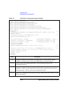
Compensation
coefficients
Explanation
R (Ω)L (H)C (F)
C2H
C2L
C3H
C3L