


4-20 Agilent B2200 User’s Guide, Edition 2
Programming
Capacitance Compensation
Capacitance Compensation
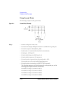
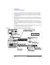
When the capacitance/conductance measurement is performed through the Agilent
B2200, LCR meter measures the capacitance/conductance of the path including a
device under test (DUT), matrix switches, extension cables and so on. So, the data
measured by the LCR meter is far from the DUT’s capacitance/conductance.
The Agilent B2200 VXIplug&play driver provides the functions used to
compensate the capacitance/conductance measured by the Agilent 4284A LCR
meter in the measurement environments described in “Required Conditions” on
page 4-21.
This section explains how to use the capacitance compensation function.
• “Capacitance Compensation Function”
• “Required Conditions”
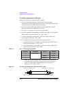
• “To Create Compensation Data File”
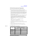
• “To Perform Measurement and Compensation”
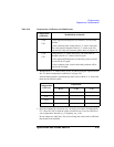
Capacitance Compensation Function
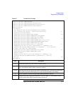
Driver functions used for the capacitance compensation are listed below.
• agb220xa_selectCompenFile function
• agb220xa_compenC function
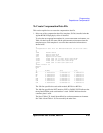
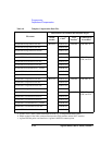
NOTE Corrected data by the function is not guaranteed. But typical data (supplemental
data) is as follows.
Capacitance measurement accuracy (typical): ±1 % ±0.5 pF
This typical data is for the following measurement conditions:
Measurement frequency: 1 kHz to 1 MHz
Measurement range: Maximum 1000 pF
Measurement terminal: At the end of the Agilent 16494A/B/C cable connected
to the switch module output terminals.
The typical data does not apply to anything extended from the 16494A/B/C cable.
The conditions described in “Required Conditions” on page 4-21 must be satisfied.