


3-22 Agilent B2200 User’s Guide, Edition 2
Front Panel Operation
Display Functions
Display Functions
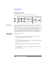
The Agilent B2200 provides LED matrix, LCD, and 18 front panel keys for front
panel operation. This section explains the display of the LED matrix and the LCD.
• “LED Matrix”
•“LCD”
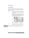
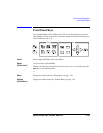
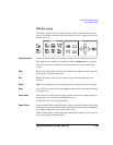
LED Matrix
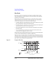
Agilent B2200 has four blocks of 14 × 12 LED matrix. They display the switch
condition of the switch modules installed in the slot 1 to slot 4. See Table 3-3.
Also LEDs labeled Card 1 to Card 4 are located above the LED matrices. They
indicate the status of the module installed in the slot 1 to 4, respectively. See Table
3-4.
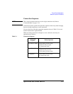
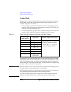
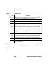
Table 3-3 LED Matrix
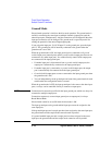
Table 3-4 Card 1/2/3/4 LED
LED color Explanation
Green The switch has been closed to connect the output channel to the
input port.
Red The switch has been closed to connect the output channel to the
input bias port or the input ground port.
Orange The LED also blinks. The switch condition can be changed by the
Open/Close key.
- The LED lights out. The switch has been opened.
LED color Explanation
Red The switch module has failed the selftest or the diagnostics.
Green The switch module has operated normally.
- The LED lights out. No switch module has been installed in this
slot.