Internal Drives in Servers 73
Internal Drives in Servers
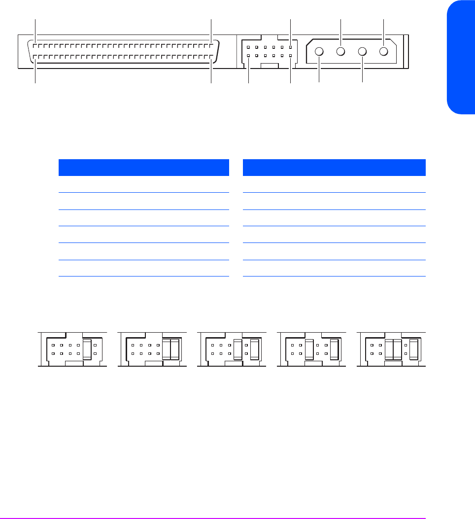
The auxiliary connector is used for setting the SCSI address and potentially as
an Enhanced Serial Interface (ESI). The pins are as follows:
The following diagram shows jumper settings for a few example SCSI IDs:
To connect an internal drive:
1 Attach a spare power cable from the computer’s internal power supply to
the power connector.
2 Attach a spare connector on the computer or HBA’s SCSI ribbon cable to
the SCSI connector of the drive.
3 If the drive is the last device on the SCSI chain, make sure that the SCSI
cable is terminated correctly.
LVD 68-pin
pin 34
pin 68
pin 1
pin 35
pin1
pin 12 pin 2
5V
5V GND
Power
SCSI ID
&ESI
12V GND
12V
Pin Signal Description Pin Signal Description
1
SEL0-
SCSI ID 0 (active low) 7
SEL3-
SCSI ID 3 (active low)
2
GND
Ground 8
GND
Ground
3
SEL1-
SCSI ID 1 (active low) 9
ESIS-
ESI active (active low)
4
GND
Ground 10
ESI0-
ESI Pin 0 (active low)
5
SEL2-
SCSI ID 2 (active low) 11
ESI1-
ESI Pin 1 (active low)
6
GND
Ground 12
3.3V
3.3V (supplied by drive)
NC 1248
235913
NC 1248NC1248NC1248NC1248


