


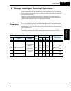

“B” Group: Fine-Tuning Functions
Configuring Drive
Parameters
3–38
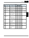
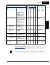
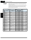
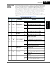
Miscellaneous functions, continued...
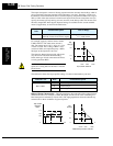
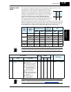
B083: Carrier frequency adjustment – The internal switching frequency of the inverter
circuitry (also called the chopper frequency). It is called the carrier frequency because the
lower AC output frequency of the inverter “rides” the carrier. The faint, high-pitched sound
you hear when the inverter is in Run Mode is characteristic of switching power supplies in
general. The carrier frequency is adjustable from 500 Hz to 12 kHz (the upper limit varies,
depending on the inverter rating). The audible sound decreases at the higher frequencies, but
RFI noise and leakage current may be increased. Refer to the specification derating curves in
Chapter 1 to determine the maximum allowable carrier frequency setting for your particular
inverter and environmental conditions.
NOTE: The carrier frequency setting must stay within specified limits for inverter-motor appli-
cations that must comply with particular regulatory agencies. For example, a European CE-
approved application requires the inverter carrier to be less than 5 kHz.
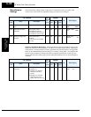
B084, B085: Initialization codes – These functions allow you to restore the factory default
settings. Please refer to “
Restoring Factory Default Settings” on page 6–9.
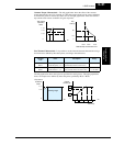
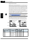
B086: Frequency display scaling – You can convert the output frequency monitor on D001 to
a scaled number (engineering units) monitored at function D007. For example, the motor may
run a conveyor that is monitored in feet per minute. Use this formula:
Scaled output frequency (D007) Output frequency (D001) Factor (B086)×=