


Using Intelligent Output Terminals
Operations
and Monitoring
4–48
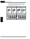
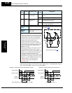
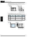
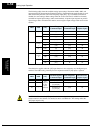
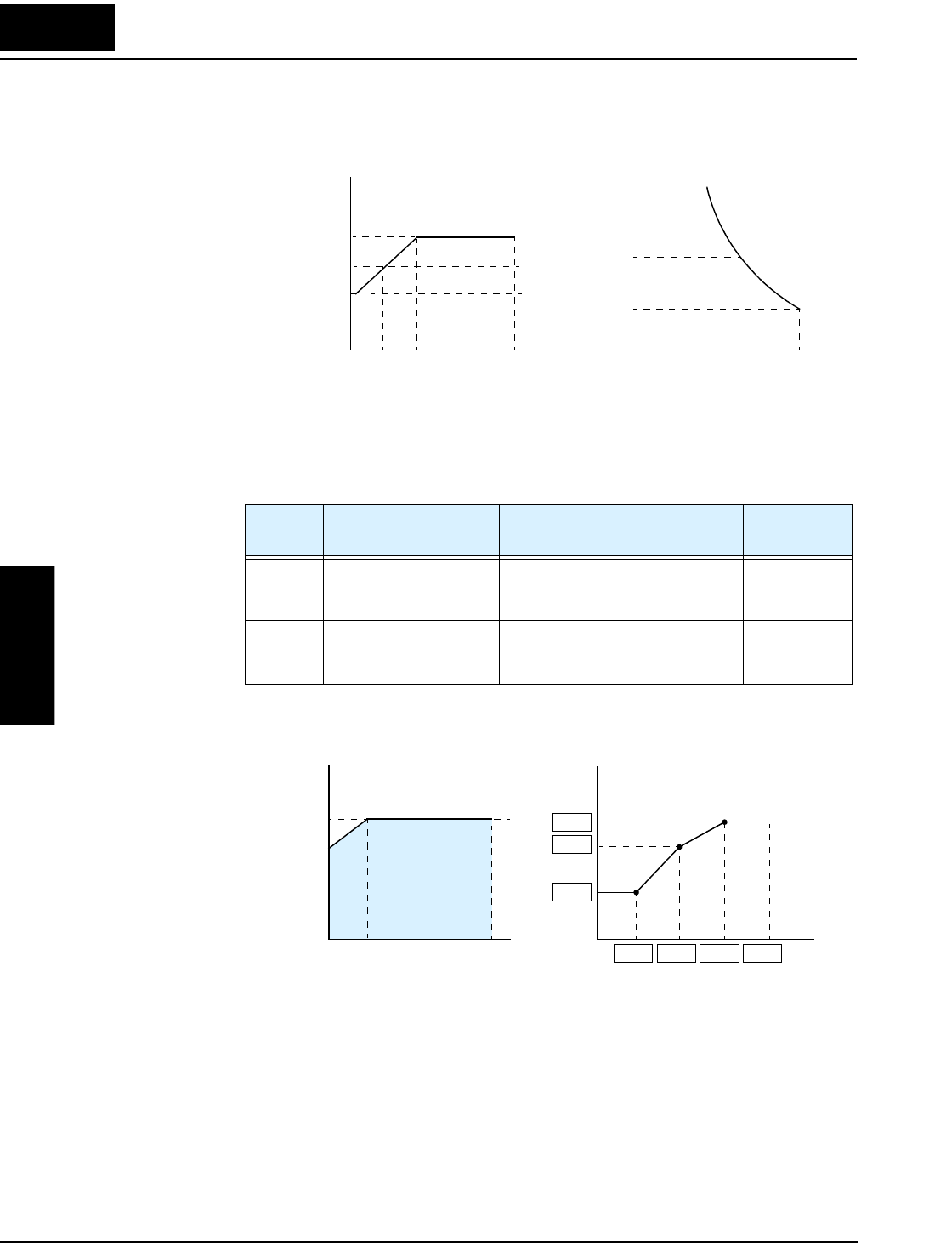
Constant Torque Characteristic – The left graph below shows the effect of the constant
torque characteristic curve. For example, at 2.5Hz, the output current level to cause overheating
in a fixed time period is reduced by a factor of 0.9. The right graph below shows the reduced
trip current levels in those conditions for given trip times.
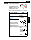
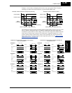
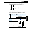
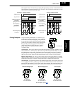
Free Thermal Characteristic - It is possible to set the electronic thermal characteristic using a
free-form curve defined by three data points, according to the table below.
The left graph below shows the region for possible free-setting curves. The right graph below
shows an example curve defined by three data points specified by B015 – B020.
Function
Code
Name Description Range
B015 /
B017 /
B019
Free-setting electronic
thermal frequency 1, 2, 3
Data point coordinates for Hz axis
(horizontal) in the free-form curve
0 to 400Hz
B016 /
B018 /
B020
Free setting electronic
thermal current 1, 2, 3
Data point coordinates for Ampere
axis (vertical) in the free-form curve
0.0 = (disable)
0.1 to 1000.
Tr ip
time (s)
60
104%
0.5
0
45.9 47.5 54.9
108% 125%
A
x 1.0
x 0.8
0
2.5 5 60
Hz
x 0.9
Reduced trip current at 2.5 Hz
Trip current
reduction
factor
Output
current (A)
0
Hz
max. freq.
B020
B018
B016
B015 B017 B019 Ax04
x 1.0
0
400
Hz
x 0.8
Setting range
Trip current
reduction
factor
5
Output freq.