


L300P Inverter
Operations
and Monitoring
4–49
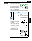
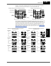
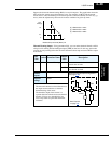
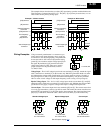
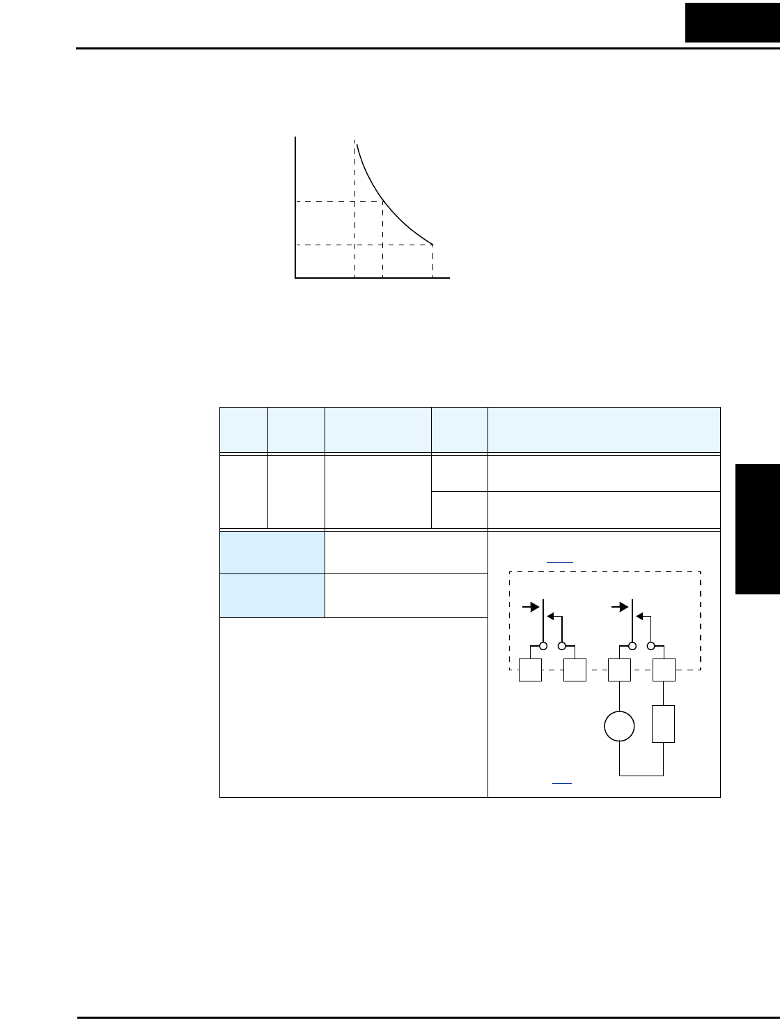
Suppose the electronic thermal setting (B012) is set to 44 Amperes. The graph below shows the
effect of the free setting torque characteristic curve. For example, at (B017) Hz, the output
current level to cause overheating in a fixed time period is reduced to (B018) A. Points (x), (y),
and (z) show the adjusted trip current levels in those conditions for given trip times.
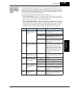
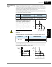
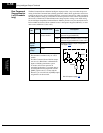
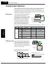
Thermal Warning Output – Using parameter C061, you can set the threshold from 0 to 100%
of trip level for turning ON the intelligent output [THM] at that level. In this way, the inverter
provides an early warning before the electronic thermal overload trips and turns OFF the output
to the motor.
Opt.
Code
Symbol Function Name
Output
State
Description
13 THM Thermal Warning ON when the electronic thermal calculation
exceeds the set limit
OFF when the electronic thermal calculation is
less than the set limit
Valid for
outputs:
11, 12, AL0 – AL2
Required
settings:
C061
Notes:
• The electronic thermal overload function uses
the output current and time to calculate
thermal heating of the motor.
• The thermistor input of the inverter is a
separate function from the electronic thermal
function. You can set a threshold for it to
cause a trip alarm at a particular thermistor
resistance.
Tr ip
time (s)
60
0.5
0
(x) (y) (z)
A
(x) = B018 value x 116%
(y) = B018 value x 120%
(z) = B018 value x 150%
Reduced trip current at (B017) Hz
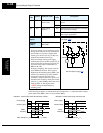
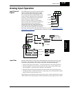
THM
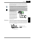
See I/O specs
on page 4–8
.
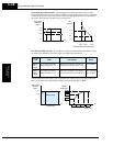
Inverter output terminal circuit
12C 12A 11C 11A
24VDC
L
Example (requires output configuration—
see page 3–48
):
+
–