


Using Intelligent Output Terminals
Operations
and Monitoring
4–40
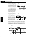
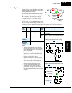
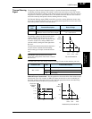
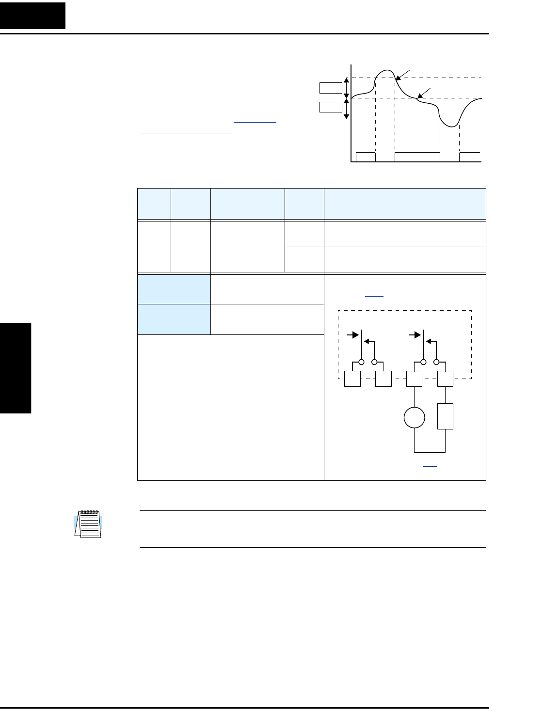
Output Deviation
for PID Control
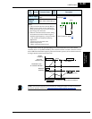
The PID loop error is defined as the
magnitude (absolute value) of the differ-
ence between the Setpoint (target value)
and the Process Variable (actual value).
When the error magnitude exceeds the
preset value for C044, the [OD] terminal
signal turns ON. Refer to “
PID Loop
Operation” on page 4–58.
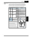
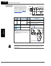
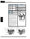
NOTE: The example circuit in the table above drives a relay coil. Note the use of a diode to
prevent the negative-going turn-off spike generated by the coil from damaging the inverter’s
output transistor.
Opt.
Code
Symbol Function Name
Output
State
Description
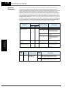
04 OD Output deviation
for PID control
ON when PID error is more than the set
threshold for the deviation signal
OFF when PID error is less than the set thresh-
old for the deviation signal
Valid for
outputs:
11, 12, AL0 – AL2
Required
settings:
C044
Notes:
• The default deviation value is set to 3%. To
change this value, change parameter C044
(deviation level).
Process variable
Set
value
[OD]
Signal
Setpoint
Error
(SP-PV)
C044
C044
ON ON
t
OD
See I/O specs on page 4–8.
Inverter output terminal circuit
12C 12A 11C 11A
24VDC
L
Example (requires output configuration—
see page 3–48
):
+
–