


Using Intelligent Input Terminals
Operations
and Monitoring
4–32
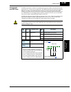
Overload
Restriction
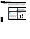
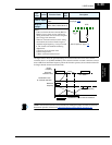
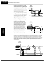
The inverter constantly monitors the motor current during acceleration, deceleration, and
constant speed. If the inverter reaches the overload restriction level, it adjusts the output
frequency automatically to limit the amount of overload. This function prevents an over-current
trip by inertia during rapid acceleration or large changes in load at constant speed. It also
attempts to prevent an over-voltage trip on deceleration due to regeneration. It accomplishes
this by temporarily suspending deceleration and/or increasing the frequency in order to dissi-
pate regenerative energy. Once the DC bus voltage falls sufficiently, deceleration will resume.
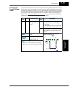
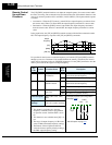
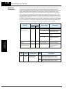
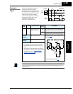
OLR Parameter Selection – Two sets of overload restriction parameter settings and values are
available as outlined in the table below. Use the B021—B026 group of settings to configure the
two set of parameters as needed. By assigning the Overload Restriction function [OLR] to an
intelligent terminal, you can select the set of restriction parameters that is in effect.
.
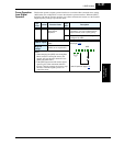
Function
Function Code
Data or Range Description
Set 1 Set 2
Overload Restriction
Operation Mode
B021 B024 00 Disable
01 Enabled during accel
and constant speed
02 Enabled during constant
speed
03 Enabled during accel,
constant speed, and
decel
Overload Restriction
Setting
B022 B025 Rated current * 0.5
to rated current * 2
Current value at which
the restriction begins
Deceleration Rate at
Overload Restriction
B023 B026 0.1 to 30 seconds Deceleration time when
overload restriction
operates
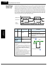
Opt.
Code
Symbol Function Name
Input
State
Description
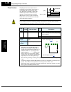
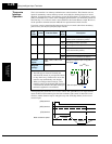
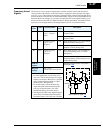
39 OLR Overload Restric-
tion Selection
ON Selects Overload Restriction Set 2,
B024, B025, B026 settings in effect
OFF Selects Overload Restriction Set 1,
B021, B022, B023 settings in effect