Orientation to Inverter Features
Inverter Mounting
and Installation
2–2
Orientation to Inverter Features
Unpacking and
Inspection
Please take a few moments to unpack your new L300P inverter and perform these steps:
1. Look for any damage that may have occurred during shipping.
2. Verify the contents of the box include:
a. One L300P inverter
b. One Instruction Manual (supplied by printed book for –FU2/–FR models, supplied on
CR-ROM for –FE2 models)
c. One L300P Quick Reference Guide
d. One packet of desiccant—discard (not for human consumption)
3. Inspect the specifications label on the front or side of the inverter. Make sure it matches the
product part number you ordered.
Main Physical
Features
The L300P Series inverters vary in size according to the current output rating and motor size for
each model number. All feature the same basic keypad and connector interface for consistent
ease of use. The inverter construction has a heat sink at the back of the housing. The fans
enhance heat sink performance. Mounting holes are pre-drilled in the heat sink for your conve-
nience. Never touch the heat sink during or just after operation; it can be very hot.
The electronics housing and front panel are built onto the front of the heat sink. The front panel
has three levels of physical access designed for convenience and safety:
• First-level access – for basic use of inverter and editing parameters during powered opera-
tion (power is ON)
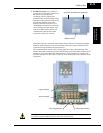
• Second-level access – for wiring the inverter power supply or motor (power is OFF)
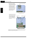
• Third-level access – for accessing the expansion bay for adding/removing expansion boards
(power is OFF)
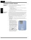
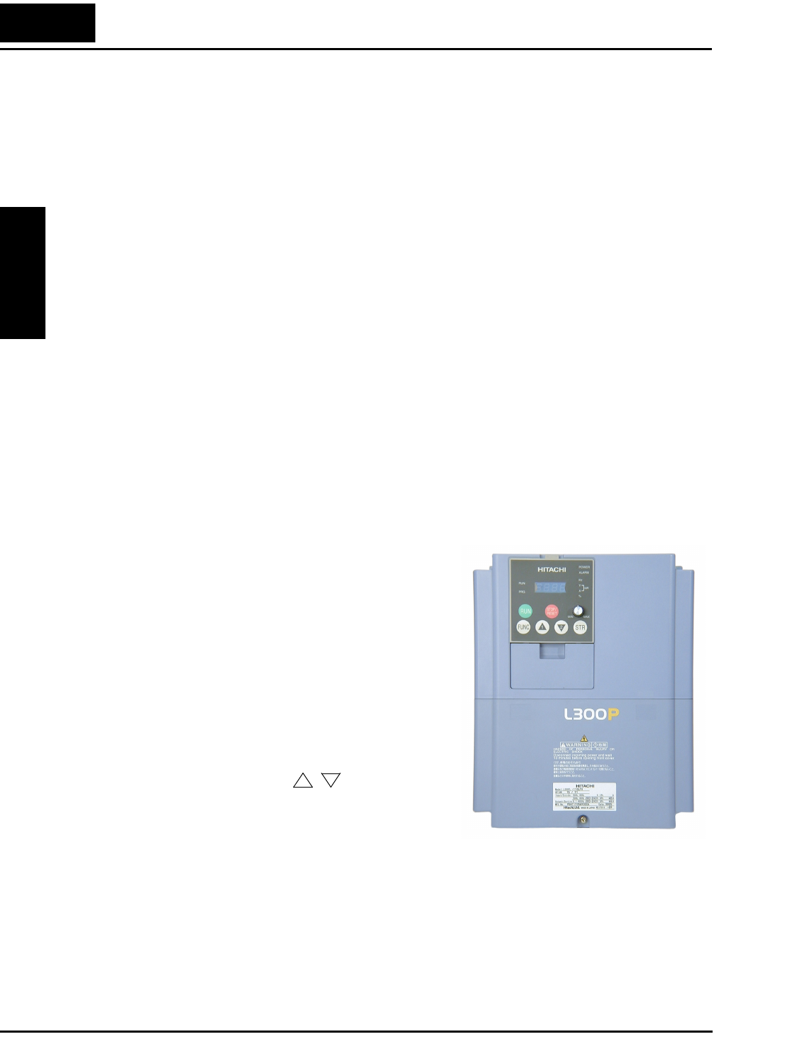
1. First-level Access - View the unit just as it
came from the box as shown. The
OPE-SRE or OPE-SR digital operator
keypad comes installed in the inverter. The
four-digit display can show a variety of
performance parameters. LEDs indicate
whether the display units are Hertz, Volts,
Amperes, or kW. Other LEDs indicate
Power (external), and Run/Stop Mode and
Program/Monitor Mode status. Membrane
keys Run and Stop/Reset, and a Min/Max
frequency control knob control motor
operation. These controls and indicators
are usually the only ones needed after the
inverter installation is complete.
The FUNC., , , and STR keys
allow an operator to change the inverter’s
functions and parameter values, or to select
the one monitored on the 4-digit display.
Note that some parameters may not be
edited if the inverter is in Run mode.
1
2


