


Analog Output Operation
Operations
and Monitoring
4–56
[AM] and [AMI]
Terminals
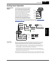
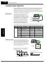
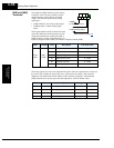
The [AM] and [AMI] terminals provide signals
to monitor various inverter parameters such as
output frequency, output current, and output
voltage. The terminals provide these analog
signal types:
• [AM] terminal: 0–10V analog output signal
• [AMI] terminal: 4–20mA analog output
signal
These signals both use the [L] terminal for signal
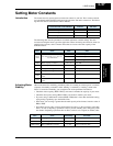
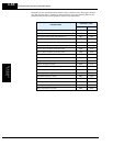
return. Six different inverter parameters may be
monitored independently at either the [AM] or
[AMI] terminal, as listed in the table below. Use
C028 to configure terminal [AM], and C029 to configure terminal [AMI].
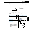
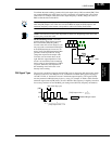
The analog signals may need some adjustment for gain or offset to compensate for variances in
the system. For example, the signals may drive a panel meter and require a full-scale gain
adjustment. The table below lists the function codes and their descriptions. The [AM] and
[AMI] terminals have separate gain and offset adjustments. Note the default values.
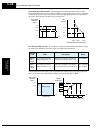
Func. Terminal Code Description Full Scale Value
C028 /
C029
[AM] /
[AMI]
00 Output frequency 0 – Max. frequency (Hz)
01 Output current 0 – 200%
04 Output voltage 0 – 100%
05 Input electric power 0 – 200%
06 Thermal load ratio 0 – 100%
07 LAD frequency 0 – Max. frequency (Hz)
Func. Terminal Description Range Default
B080 [AM] Gain adjustment 0 – 255 180
C086 [AM] Offset Adjustment 0.0 – 10.0V 0.0V
C087 [AMI] Gain adjustment 0 – 255 80
C088 [AMI] Offset Adjustment 0.0 – 20.0mA 0.0mA
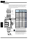
H O2
FM
AM
O OIL
AMI
A GND
See I/O specs on page 4–8
0–10V analog output
4–20mA analog output