


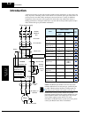
L300P Inverter
Motor Control
Accessories
5–9
Selecting a
Braking Resistor
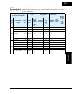
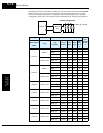
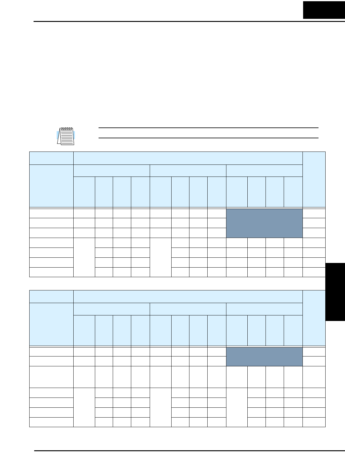
You can add one or more resistors to your inverter configuration to increase braking torque
performance. The number of resistors and their configuration (series or parallel) depends on the
desired braking torque. The tables below list the resistor types for inverter models with internal
braking units. Tables for inverters with external braking units are on the next two pages.
• Total Ohms – lists the resistance value of the resistor or, if using multiple resistors, their
combined resistance
• Total Watts – lists the power dissipation of the resistor or, if using multiple resistors, their
combined power dissipation
• Maximum Duty Cycle – the maximum allowable percentage of braking time over any 100-
second interval to avoid overheating the resistor(s)
• Maximum braking torque – the maximum braking torque that the inverter / resistor combina-
tion can deliver
NOTE: If your application requires resistors with NEMA ratings, be sure to use the HRB type.
200V Class Dynamic Braking Resistor Selection
Max.
Braking
Torque,
%
Model Number
L300P
JRB Series SRB/NSRB Series HRB Series
Type
& (qty)
Total
Ohms
Total
Watts
Max.
Duty
Cycle,
%
Type
& (qty)
Total
Ohms
Total
Watts
Max.
Duty
Cycle,
%
Type
& (qty)
Total
Ohms
Total
Watts
Max.
Duty
Cycle,
%
–015LFU2 120–4 35 120 1.0 400–1 35 400 7.5
200
–022LFU2 120–4 35 120 1.0 400–1 35 400 7.5 160
–037LFU2 120–4 35 120 1.0 400–1 35 400 7.5 100
–055LFU2
120–4
x (2) in
parallel
17.5 240 1.0
400–1
x (2) in
parallel
17.5 800 7.5 HRB3 17 1200 10 80
–075LFU2 17.5 240 1.0 17.5 800 7.5 HRB3 17 1200 10 80
–110LFU2 17.5 240 1.0 17.5 800 7.5 HRB3 17 1200 10 55
–150LFU2 17.5 240 1.0 17.5 800 7.5 HRB3 17 1200 10 50
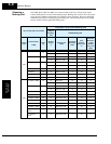
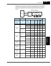
400V Class Dynamic Braking Resistor Selection
Max.
Braking
Torque,
%
Model Number
L300P
JRB Series SRB/NSRB Series HRB Series
Type
& (qty)
Total
Ohms
Total
Watts
Max.
Duty
Cycle,
%
Type
& (qty)
Total
Ohms
Total
Watts
Max.
Duty
Cycle,
%
Type
& (qty)
Total
Ohms
Total
Watts
Max.
Duty
Cycle,
%
–015HFU2, HFE2 120–2 100 120 1.5 200–2 100 200 7.5
200
–022HFU2, HFE2 120–2 100 120 1.5 200–2 100 200 7.5 200
–040HFU2, HFE2 120–2 100 120 1.5 200–2 100 200 7.5 HRB2
x (2) in
series
100 800 10 140
–055HFU2, HFE2
120–4
x (2) in
series
70 240 1.0
400–1
x (2) in
series
70 800 7.5 HRB2
x (2) in
series
70 1200 10 120
–075HFU2, HFE2 70 240 1.0 70 800 7.5 70 1200 10 100
–110HFU2, HFE2 70 240 1.0 70 800 7.5 70 1200 10 55
–150HFU2, HFE2 70 240 1.0 70 800 7.5 70 1200 10 50