


Communications Protocol
Appendix B
B–10
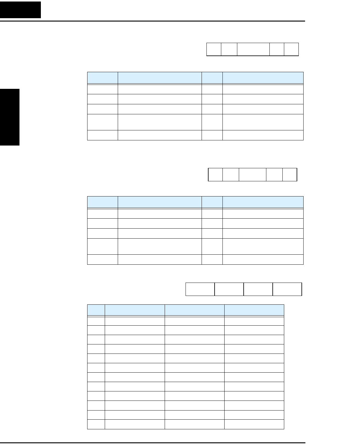
Command – 04 The 04 command reads the status of the inverter.
The frame format of command 04 follows the
diagrams and specification tables. The transmit
frame has no data field.
The receive frame has an 8-byte data field,
containing values for three trip items (plus a
reserved field).
Trip data is organized as shown. The
table below lists the codes and their
meanings.
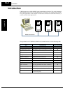
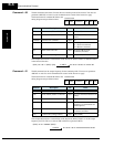
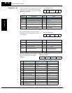
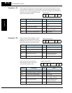
Element Description Size Value
STX Control code (STart of TeXt) 1 byte STX (0x02)
Node Node (station) address of inverter 2 bytes 01 to 32
Command Transmission command 2 bytes 04
BCC Block check sum code 2 bytes Exclusive OR of Node,
Command, and Data
[CR] Control code (carriage return) 1 byte [CR] (0x0D)
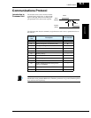
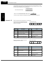
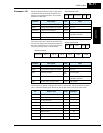
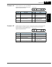
Element Description Size Value
STX Control code (STart of TeXt) 1 byte STX (0x02)
Node Node (station) address of inverter 2 bytes 01 to 32
Data Transmission data 8 bytes (see next table)
BCC Block check sum code 2 bytes Exclusive OR of Node,
Command, and Data
[CR] Control code (carriage return) 1 byte [CR] (0x0D)
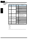
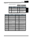
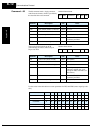
Code Status A Definition Status B Definition Status C Definition
00 Initial status On stopping —
01 VDC waiting settlement On running Stop
02 On Stopping On tripping Deceleration speed
03 On running — Constant speed
04 On free-run stop — Acceleration speed
05 On jog — Forward
06 On dynamic braking — Reverse
07 On reading motor freq. — Reverse from forward
08 On retry — Forward from reverse
09 On under-voltage — Forward start
10 On trip — Reverse start
11 On waiting reset — —
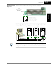
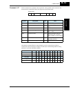
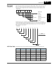
STX Node Command BCC [CR]
Transmit frame format
STX
Node Data BCC [CR]
Receive frame format
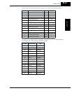
Data field contents
(reserved)Status CStatus B
Status A