


Using Intelligent Output Terminals
Operations
and Monitoring
4–36
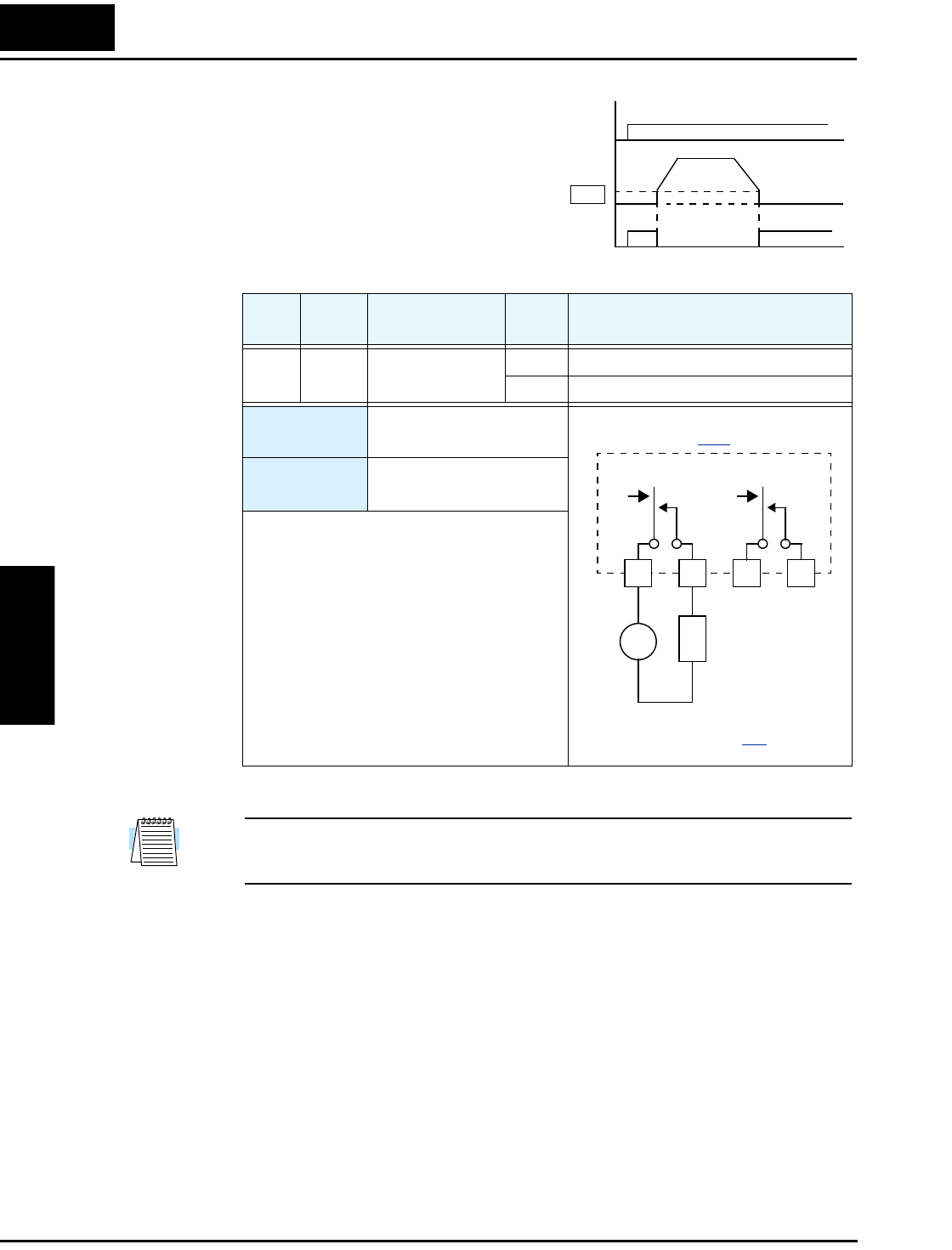
Run Signal When the [RUN] signal is selected as an
intelligent output terminal, the inverter
outputs a signal on that terminal when it is
in Run Mode. The output logic is active
low, and is the open collector type (switch
to common).
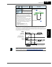
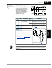
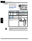
NOTE: The example circuit in the table above drives a relay coil. Note the use of a diode to
prevent the negative-going turn-off spike generated by the coil from damaging the inverter’s
output transistor.
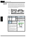
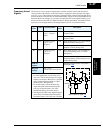
Opt.
Code
Symbol Function Name
Output
State
Description
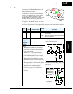
00 RUN Run signal ON when inverter is in Run Mode
OFF when inverter is in Stop Mode
Valid for
outputs:
11, 12, AL0 – AL2
Required
settings:
(none)
Notes:
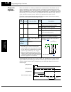
• The inverter outputs the [RUN] signal
whenever the inverter output exceeds the start
frequency specified by parameter B082. The
start frequency is the initial inverter output
frequency when it turns ON.
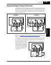
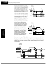
[FW, RV]
Motor
speed
Run
Signal
start freq.
B82
ON
t
RUN
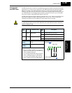
See I/O specs on page 4–8.
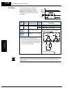
Inverter output terminal circuit
12C 12A 11C 11A
24VDC
L
Example: (default output configuration
shown—see page 3–48):
+
–