


Optional Alarm Output at Power Loss
Operations
and Monitoring
4–4
Optional Alarm Output at Power Loss
With the default L300P inverter configuration, a sudden power loss will cause the inverter to
shut down immediately. If running at the time, the motor and load will coast to a stop. And
without power, the inverter’s alarm output will not activate. This default performance may be
fine for applications with loads such as fans and pumps. However, you may want an alarm
signal upon power loss. This section describes how to harness regenerative energy so that the
motor/load actually powers the inverter long enough to power the alarm output.
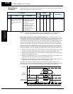
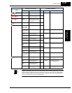
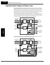
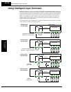
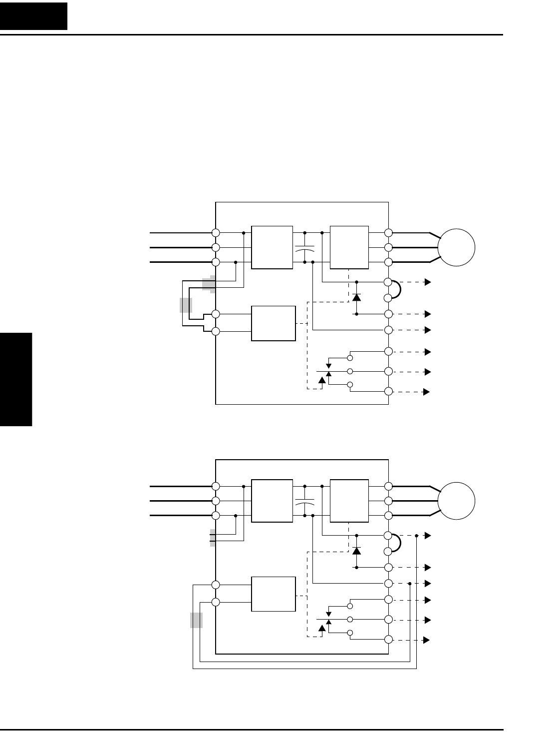
The diagram below shows the default configuration. Chapter 2 covered wiring the power source
to the inverter input and the inverter output to the motor. By default, the inverter’s internal
control circuit gets its power from two phases (R and T) from the input. The user-accessible 2-
wire jumper (R–R0 and T–T0) connects input power to the control circuit.
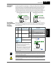
To provide power to the control circuit after input power loss, you must change the control
circuit wiring as shown below (steps provided on following page).
U
V
W
Motor
R
S
T
T
R
R0
T0
Power source,
3-phase
2-wire
jumper
P
PD
RB
N
To optional
braking resistor /
braking unit
Control
circuit
Rectifier Inverter
Converter
DC bus
+
–
+
–
J51
Ferrite
filter
L300P
AL0
AL2
AL1
To external
alarm circuit or
interface
U
V
W
Motor
R
S
T
T
R
R0
T0
Power source,
3-phase
2-wire
jumper,
20AWG
P
PD
RB
N
To optional
braking resistor /
braking unit
Control
circuit
Rectifier Inverter
Converter
DC bus
+
–
+
–
J51
Ferrite
filter
L300P
AL0
AL2
AL1
To external
alarm circuit or
interface