


L300P Inverter
Appendix B
B–3
Serial Connection
Diagrams
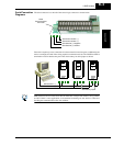
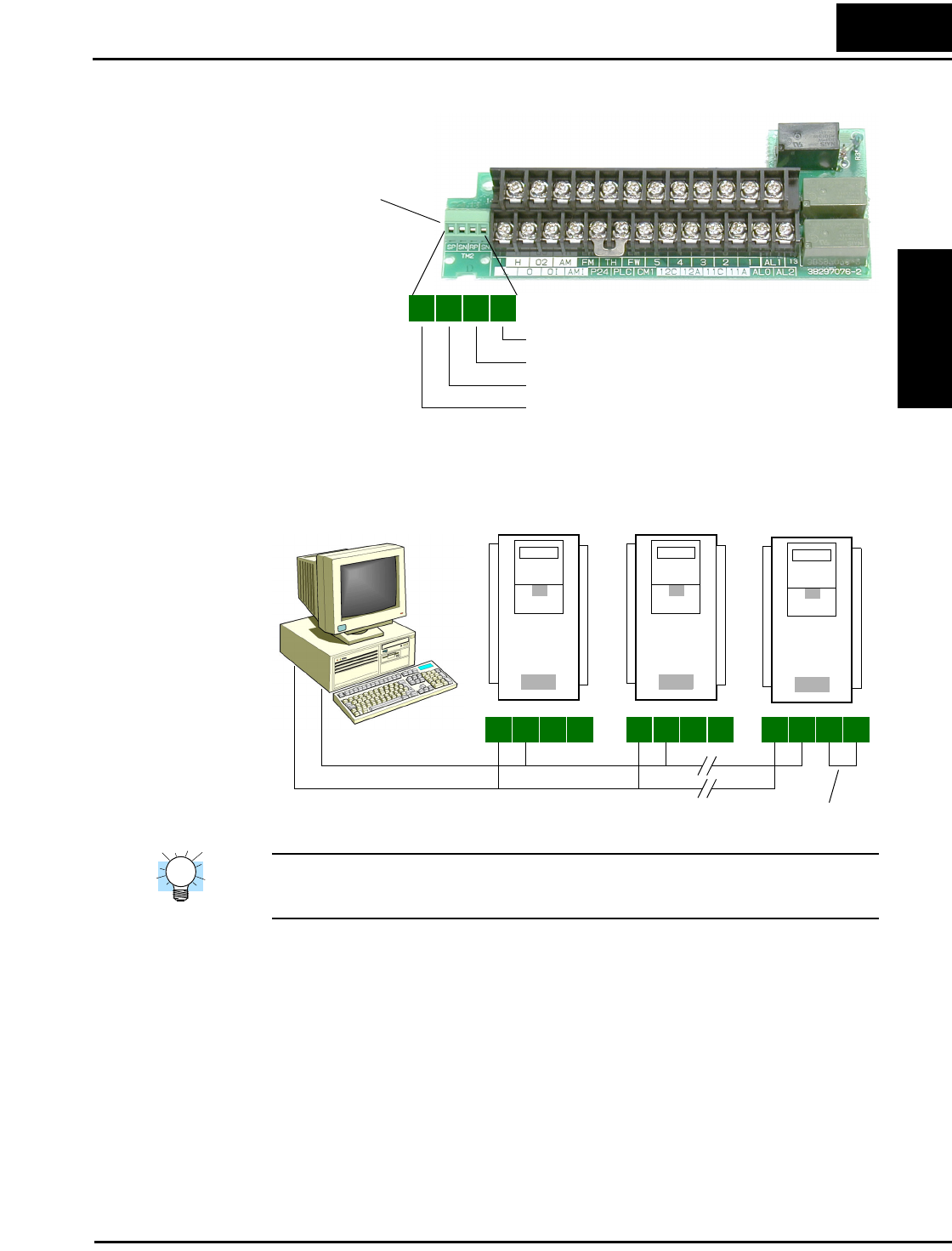
The serial connector is to the left of the control logic connector as shown below:
Each device requires just two connections for data transmission and reception. Additionally, the
device at each physical end of the wiring requires a termination resistor. The L300P has built-in
termination resistors that become part of the circuit when you add a jumper as shown.
TIP: Each slave device on the serial network must have a unique node address, set by parame-
ter C072. If this is a new application, we recommend connecting one new device at a time and
checking the communications after each addition.
SP SN RP SN
Serial
Communications
Connector
Send/receive (+) Positive
Send/receive (–) Negative
Termination resistor (+)
Termination resistor (–)
SP SN RP SN
L300P L300P
SP SN RP SN SP SN RP SN
L300P
Termination jumper
Send/receive (+)
Send/receive (–)