


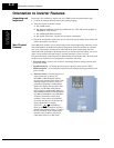
Orientation to Inverter Features
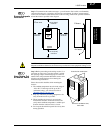
Inverter Mounting
and Installation
2–4
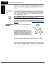
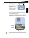
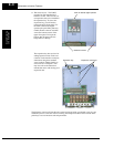
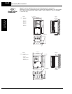
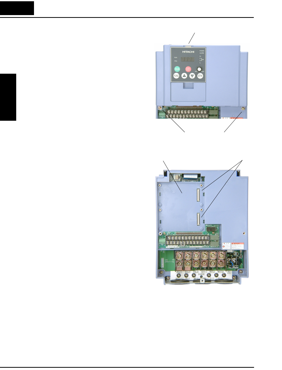
3. Third-level access - The L300P
provides for field installation of
interface circuits. These circuits are
on expansion cards, to be installed in
the expansion bay. To access the
expansion bay, you will need to
remove the upper front panel. Use
the latch to release the digital
operator (the panel filler plate may
remain). Remove the two retention
screws the bottom corners of the
upper front panel. Lift up at the
bottom, then disengage the two
hinge latches at the top.
The expansion bay has two sites for
adding expansion cards. Each card
connects via the interface connector,
and mounts using three standoff
screw locations. Further details on
accessories are in Chapter 5. You
may also refer to the instruction
manual that comes with each type of
expansion card.
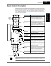
The following sections will describe the system design and guide you through a step-by-step
installation process. After the section on wiring, this chapter will show how to use the front
panel keys to access functions and edit parameters.
Latch to release digital operator
Retention screws
Expansion bay Expansion connectors