


“A” Group: Standard Functions
Configuring Drive
Parameters
3–14
Torque Control
Algorithms
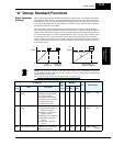
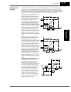
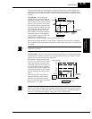
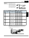
The inverter generates the motor output
according to the V/f algorithm. Parameter
A044 selects the inverter torque control
algorithm for generating the frequency
output, as shown in the diagram to the right
(A244 for 2nd motor). The factory default
is 00 (constant torque V/f control).
Review the following descriptions to help
you choose the best torque control
algorithm for your application.
• The built-in V/f curves are oriented
toward developing constant torque or
variable torque characteristics (see
graphs below).
• The free-setting curve provides an even more flexible characteristic, but it requires more
parameter settings.
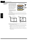
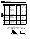
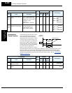
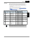
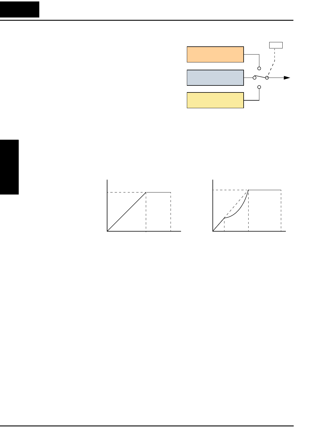
Constant and Variable Torque – The graph below (left) shows the constant torque character-
istic from 0Hz to the base frequency A003. The voltage remains constant for output frequencies
higher than the base frequency.
The graph above (right) shows the general characteristic for variable torque. The curve may be
best described in three sections, as follows:
a. The range from 0Hz to 10% of the base frequency is the constant torque characteristic.
For example, a base frequency of 60Hz ends the constant torque characteristic segment
at 6Hz.
b. The range from 10% of the base frequency to the base frequency is the variable
(reduced) torque characteristic. The voltage is output in the curve of frequency to the 1.7
power.
c. After reaching the base frequency, the characteristic maintains a constant output voltage
for higher frequencies.
Output
V/f control,
constant torque
V/f control,
variable torque
V/f control, free-
setting curve
Inverter Torque Control Algorithms
02
01
00
A044
Constant torque
0
Variable torque
0
Maximum
frequency
Base
frequency
100%
100%
Maximum
frequency
Base
frequency
Output
voltage
Output
voltage
10% of
base
frequency
a.
b. c.