


Using Intelligent Input Terminals
Operations
and Monitoring
4–30
Remote Control
Up and Down
Functions
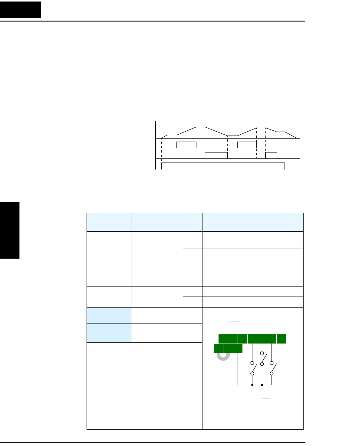
The [UP] [DWN] terminal functions can adjust the output frequency for remote control while
the motor is running. The acceleration time and deceleration time used with this function is the
same as for normal operation ACC1 and DEC1 (2ACC1,2DEC1). The input terminals operate
as follows:
• Acceleration - When the [UP] contact is turned ON, the output frequency accelerates from
the current value. When it is turned OFF, the output frequency maintains its current value.
• Deceleration - When the [DWN] contact is turned ON, the output frequency decelerates
from the current value. When it is turned OFF, the output frequency maintains its current
value.
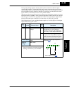
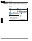
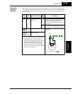
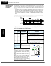
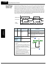
In the graph below, the [UP] and [DWN] terminals activate while the Run command remains
ON. The output frequency responds to the [UP] and [DWN] commands.
It is possible for the inverter to retain the frequency set from the [UP] and [DWN] terminals
through a power loss. Parameter C101 enables/disables the memory. If disabled, the inverter
retains the last frequency before an UP/DWN adjustment. Use the [UDC] terminal to clear the
memory and return to the original set output frequency.
Opt.
Code
Symbol Function Name
Input
State
Description
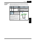
27 UP Remote Control
UP Function
ON Accelerates (increases output frequency)
motor from current frequency
OFF Output to motor operates normally
28 DWN Remote Control
DOWN Function
ON
Decelerates (decreases output frequency)
motor from current frequency
OFF Output to motor operates normally
29 UDC Remote Control
Data Clear
ON Clears the Up/down frequency memory
OFF No effect on Up/down memory
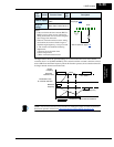
Valid for inputs:
C001, C002, C003, C004,
C005
Required
settings:
A001 = 02
C101 = 01 (enables memory)
Notes:
• This feature is available only when the
frequency command source is programmed
for operator control. Confirm A001 is set to
02.
• This function is not available when [JG] is in
use.
• The range of output frequency is 0 Hz to the
value in A004 (maximum frequency setting).
• The Remote Control Up/Down function
varies the inverter speed by directly writing to
the F001 output frequency setting.
Output
frequency
[UP]
[FW, RV]
[DWN]
t
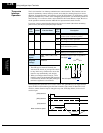
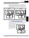
5 3 14 2
FW
TH
PLC
P24
CM1
See I/O specs on page 4–8.
UDC
DWN
UP
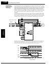
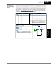
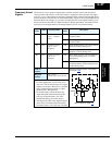
Example (requires input configuration—
see page 3–43
):