


Step-by-Step Basic Installation
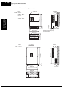
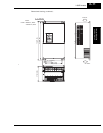
Inverter Mounting
and Installation
2–18
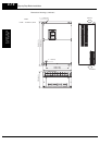
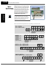
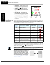
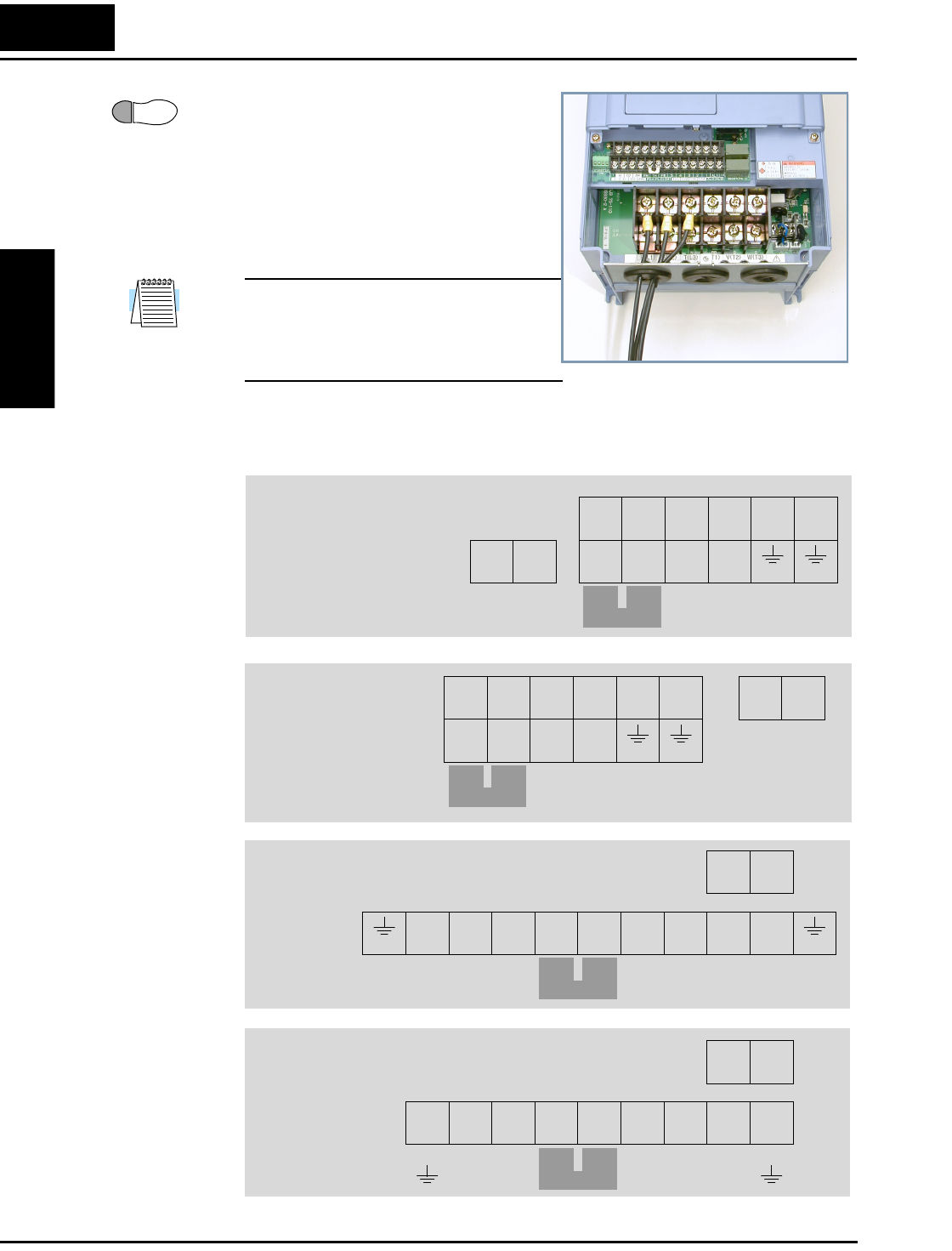
Step 6: In this step, you will connect wiring to
the input of the inverter. All models have the
same power connector terminals labeled R(L1),
S(L2), and T(L3) for three-phase input. The
three phases may be connected in any order, as
they are isolated from chassis ground and do
not determine motor direction of rotation.
Please refer to the specifications label (on
the front or side of the inverter) for the
acceptable input voltage ranges!
NOTE: The wiring example to the right shows
an L300P-110LFU2 inverter. The terminal
locations will vary, depending on the inverter
model (see below). Note the use of ring lug
connectors for a secure connection.
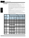
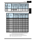
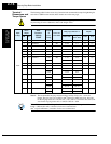
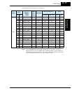
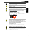
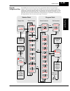
Please use the terminal arrangement below corresponding to your inverter model.
6
Wire the Inverter
Input to a Supply
R
(L1)
V
(T2)
U
(T1)
W
(T3)
S
(L2)
T
(L3)
PD
(+1)
RB
(RB)
P
(+)
N
(–) (G) (G)
R0
(R0)
T0
(T0)
R
(L1)
V
(T2)
U
(T1)
W
(T3)
S
(L2)
T
(L3)
PD
(+1)
P
(+)
N
(–)
R0
(R0)
T0
(T0)
–075LFU2
–075HFU2, HFE2
–110LFU2
–110HFU2, HFE2
–150LFU2
–150HFU2, HFE2
–220LFU2, –300LFU2,
–450 to –750LFU2, –900 to –1320HFU2, HFE2
–185LFU2, –185 to –370HFU2, HFE2
–370LFU2, –450 to –750HFU2, HFE2
R
(L1)
V
(T2)
U
(T1)
W
(T3)
S
(L2)
T
(L3)
PD
(+1)
P
(+)
N
(–) (G)(G)
R0
(R0)
T0
(T0)
Jumper
bar
Jumper
bar
Jumper
bar
R
(L1)
V
(T2)
U
(T1)
W
(T3)
S
(L2)
T
(L3)
PD
(+1)
RB
(RB)
P
(+)
N
(–) (G) (G)
R0
(R0)
T0
(T0)
–015 to –055LFU2
–015 to –055HFU2, HFE2
Jumper
bar